Send the request type, manufacturer, equipment model/year, part reference, ratings, quantity, destination, required date, and any drawing or photo notes. The SUVELL team will review the request.
Email: admin@suvell.com
Phone: +86 189 6871 1705
Factory: No.208 Wei 12 Rd, Yueqing Economic Development Zone, Wenzhou, Zhejiang, China
What Is a Ring Main Unit? Components, Functions, and Common Configurations
Understand ring main unit components and configurations, including ring feeders, transformer protection, insulation choices, extensibility and smart-RMU functions.
An RMU combines ring switching, a load or transformer branch, earthing and interlocks; its role does not prescribe one insulation medium or fixed number of ways.
Compare extensibility, protection, cable access, metering and automation as separate configuration choices against the named product’s documentation.
Verify assembly and function test evidence, cable interfaces and network integration; interlocks alone do not prove de-energisation or prevent external backfeed.
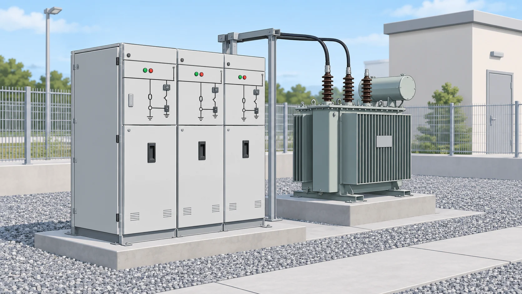
A ring main unit (RMU) is a factory-assembled, metal-enclosed switchgear set installed at a load connection point in a ring distribution network. In its conventional form it holds two ring switches — one for each cable direction of the ring — plus a transformer tee-off branch protected by a fuse switch or a circuit breaker, often with an RTU for remote monitoring and control. The defining characteristic is the function, not the insulation medium or a fixed number of ways: an RMU closes and sections a ring at a point where a transformer or other load taps off.
Because "RMU" names an assembly category rather than one product, two quotations can both be correct and still describe equipment that cannot be swapped. Reading the term as a function first and a specification second is what keeps a comparison honest.
Decision axis
Conventional RMU
Smart RMU
Core function
Ring switching, transformer tee-off, earthing
Identical switching and protection core
Switching and protection
Ring switches, fuse switch or circuit breaker, earth switch
Unchanged — the digital layer sits on top
Sensing
Minimal or none beyond protection and metering CTs
Added current, voltage, temperature or partial-discharge sensors
Communication
None, or local indication only
RTU, communications link, protocol mapping to SCADA
Fault handling
Field crew sections the ring manually
Automated fault detection and indication to shorten restoration
Evidence boundary
Manufacturer datasheet for the assembly
Datasheet plus network and cyber configuration
Conceptual engineering illustration; not a photograph of a named manufacturer product or factory.
Why the Ring Function Defines the Equipment
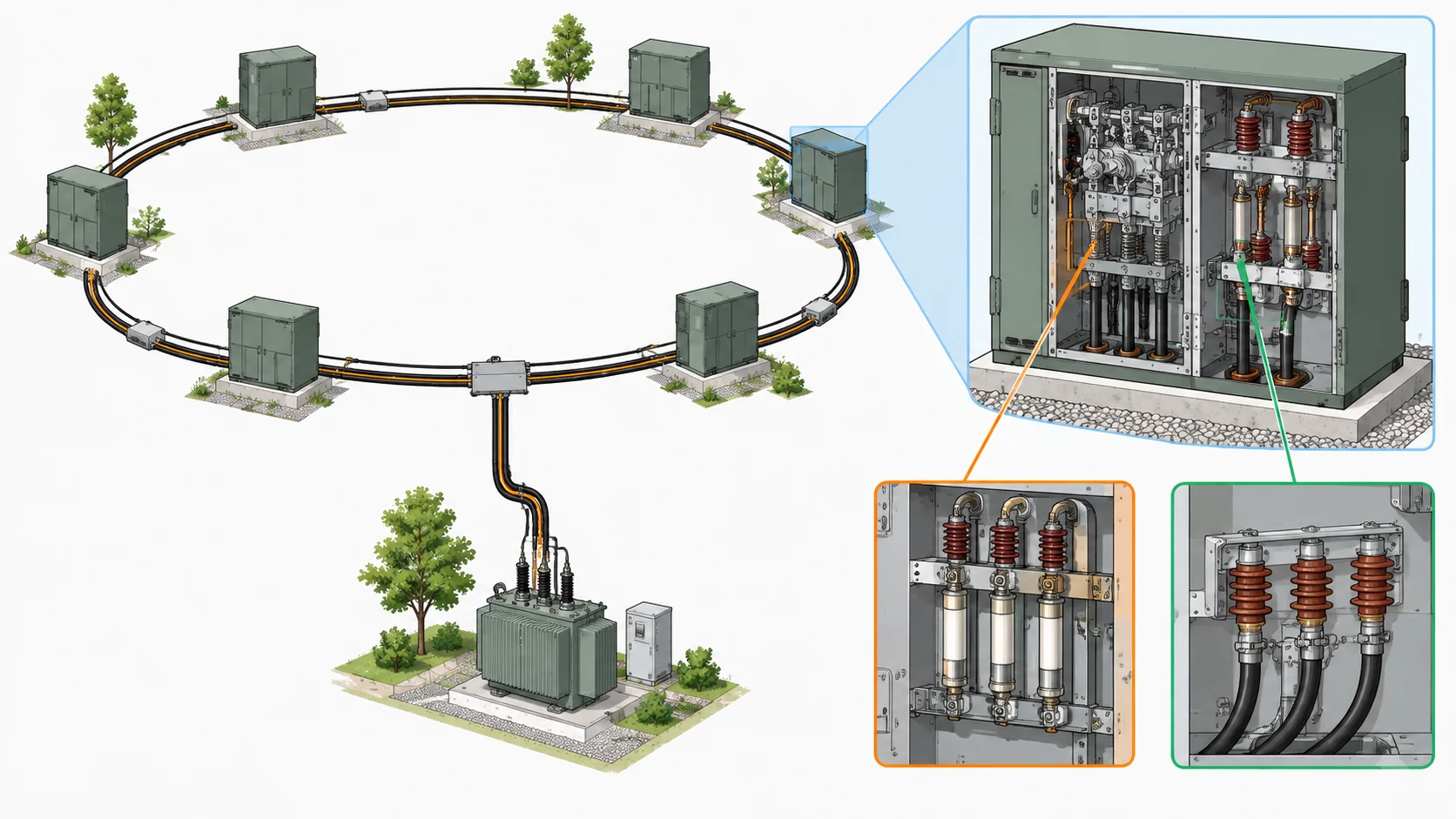
A ring layout provides potential alternative cable paths between load points and the source. Many distribution rings operate with a normally open point; restoration after a fault depends on protection, isolation, available capacity and approved network procedures. The RMU provides the switching functions used to sectionalise that layout.
At a typical load node, the two ring switches isolate the node from the ring in either direction; the tee-off feeds the transformer or the load. Isolating a faulty section is therefore a matter of operating the switches on either side of it, not building a new switching station. The ring switch is a load break switch, meaning it is selected for its ability to open and close under load current; that duty is a different rating from fault making or fault breaking, and the two are quoted separately.
The ring/transformer arrangement above is the conventional example, not a required layout. An RMU may be built with three or four ways, with or without a transformer branch, and with the tee-off protected by a fuse switch or a circuit breaker depending on the duty and the network operator's practice. Treat the arrangement as a default illustration whose applicability has to be confirmed against the actual network.
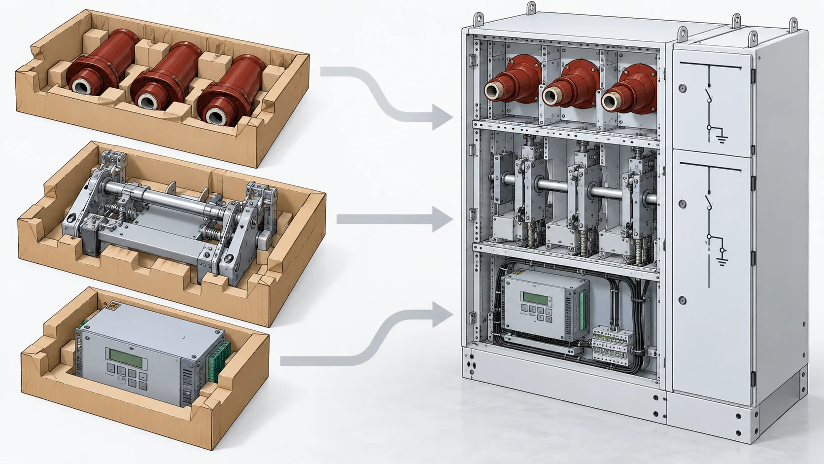
What Sits Inside an RMU
Ring switches / load break switches. The primary switching elements that connect the assembly to the ring cables. Their ratings cover rated current, load breaking, short-circuit making and short-time withstand.
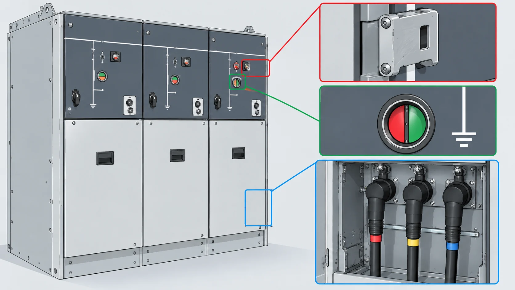
Earth switch. A separate function with its own ratings, used to earth a cable or busbar section before work. Interlocks prevent specified incompatible equipment states; they do not establish that a cable is dead or remove the possibility of an external backfeed. A three-position arrangement provides closed, open and earthed positions, subject to the approved model and network procedures.
Transformer tee-off. Either a switch-fuse combination or a circuit breaker with a protective relay. The fuse route is a one-shot device with a defined time-current curve; the relay route offers adjustable protection and, in many designs, re-closing and remote tripping through the RTU.
Cable bushings and termination interfaces. This is where the RMU meets the cable, and it is frequently the interface that decides whether a replacement fits. Bushings must match the cable type, cross-section and termination system, and with plug-in separable connectors they define the cable access direction — front or rear. Get this wrong and the switchgear is correct but unconnectable.
Operating mechanism.Manual, spring-charged or motorised, driving the load break switches and earth switch. The mechanism is also where interlocking is physically realised: electrical and mechanical interlocks between switches, earth switch and cable compartment access.
Enclosure. Metal-enclosed and, in the common design, compartmentalised. Its declared internal arc classification and vent direction belong to the specific product, not to the RMU concept.
Automation layer. Sensors, RTU and communications where remote monitoring or control is required.
Conceptual engineering illustration; not a photograph of a named manufacturer product or factory.
Common Configurations and Why They Differ
Configuration is the part of an RMU specification that varies most between manufacturers, and it is best read as a set of independent choices rather than a single grade.
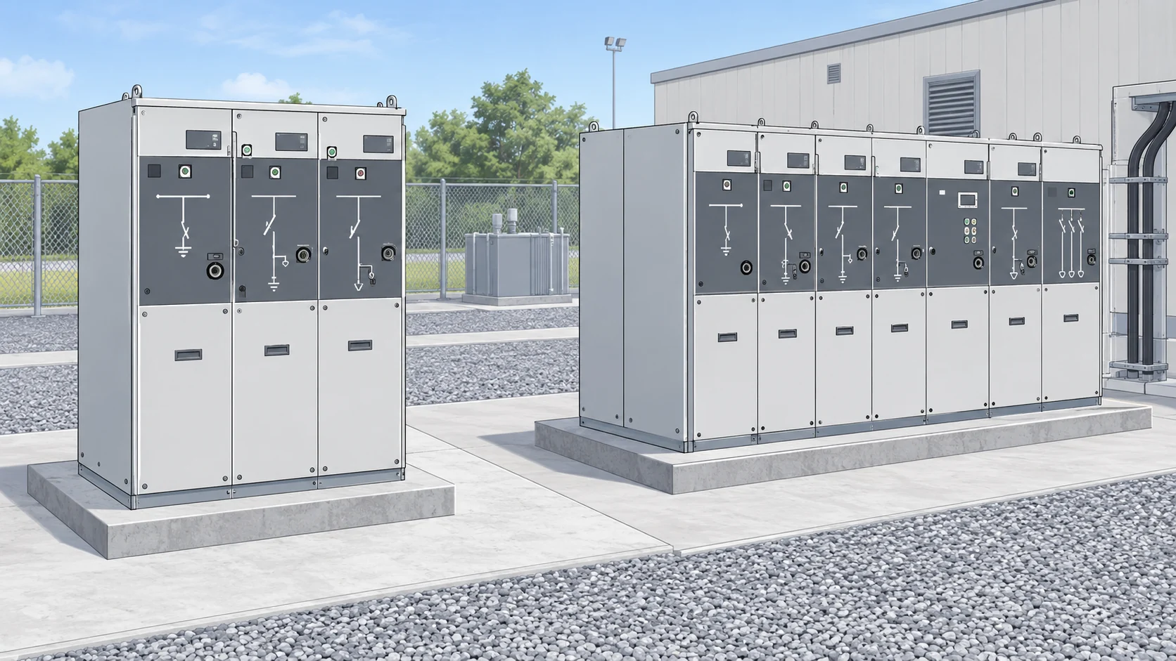
Extensible versus non-extensible. An extensible RMU can take additional units later through a busbar extension; a non-extensible one is fixed at the ways ordered. Extensibility is a capital-planning decision set at purchase, and it changes footprint, busbar arrangement and the future outage needed to add capacity.
Number of functions. Two ring ways plus one tee-off is the conventional pattern, but three- and four-function assemblies are normal, and assemblies with no transformer branch at all are used purely for cable sectioning.
Protection route. Fuse switch or circuit breaker with relay. This choice drives coordination at the upstream device, the panel's depth, and whether remote tripping is even possible.
Metering. Metering can be integrated or supplied as a separate unit with its own enclosure and current/voltage transformers. Whether metering is in scope affects the footprint and the interface to the utility's metering practice.
Cable access. Front access and rear access change the clearances required in front of the assembly and the civil layout of the cable trench.
Motorisation and automation. Manual operation, motorised operation, and motorised operation with RTU integration are three distinct scopes with different control-power and communications dependencies.
Manufacturers publish their own option structure: Lucy Electric, for example, lists extensible and non-extensible Aegis Plus RMUs with separately supplied metering units, front cable access, electrical and mechanical interlocking, motorisation, fuse or relay protection and integrated RTU options. Those options are specific to that family — the fact that a feature exists on one range says nothing about whether it is standard, optional or unavailable elsewhere.
Conceptual engineering illustration; not a photograph of a named manufacturer product or factory.
Insulation Media: Air, Oil, Gas and SF6-Free
Insulation medium is the axis most often mistaken for the definition of an RMU. It is not. The network role stays the same across air-, oil-, gas- and other insulation designs; the switching or interruption medium must be identified separately — what changes is the enclosure, the maintenance regime, the handling requirements and the approvals.
Insulation route
What it is
What must be confirmed per family
Air
Air around the primary circuit; switching medium depends on the product
Dimensions, ratings and clearances for the specific range
Oil
Immersed insulating medium
Enclosure, sealing and inspection regime for that design
Gas (SF6)
Sealed pressurised gas compartment
Gas handling, leak management and end-of-life policy
SF6-free / dry air
Alternative gas or compressed dry air
Whether ratings and interfaces match the SF6 version of the same family
Lucy Electric's current RMU portfolio spans air-, oil- and gas-insulated families plus SF6-free alternatives, for both indoor and outdoor service. ABB takes the same insulation change through its SafeRing RMU and SafePlus switchgear families, offering SF6 versions alongside dry-air SafeRing Air and SafePlus Air variants. That is an official example of a product family keeping its network role while changing its insulating medium.
The important boundary: do not infer that different insulation routes share dimensions, maintenance access, switching duties, gas handling or approvals. ABB's statements about a common interface, footprint and operation apply to its own specified families and do not license cross-brand substitution. No generic gas conversion, interchangeability or service-life claim follows from the existence of two insulation versions of one range.
Conventional and Smart RMUs: Where the Digital Layer Begins
Schneider Electric separates the switching and protection functions of a conventional RMU from what a smart RMU adds: sensors, communication, remote monitoring, RTUs and automated fault detection. That separation is the right way to buy one, because the digital layer does not change the underlying assembly and cannot compensate for a switching specification that does not match the network.
Two consequences follow. First, verify the switching assembly against the network duty on its own terms, then evaluate the digital layer separately. Second, treat automation claims as conditional. Cybersecurity posture, continuity of supply and restoration performance depend on the actual equipment and on the network and control configuration behind it, so a claim that is true for one deployment may not transfer to another.
On published figures, one caution: an overview page may quote a representative rating — Schneider Electric's smart-RMU overview uses a 24 kV / 360 A reference case — and that number describes the page's example, not a ceiling for RMUs generally. Ratings must be read from the datasheet of the named product family.
Standards: What Each Function Is Judged Against
An RMU assembly is assessed as metal-enclosed switchgear, while its installed functions also map onto relevant parts of the IEC 62271 series: circuit breakers, switches, disconnectors and earthing switches, switch-fuse combinations, and metal-enclosed switchgear each have their own part, with a further part covering prefabricated substations. A product datasheet that cites a standard per function is describing that structure accurately; a quotation should identify both the assembly standard and the standards applicable to its installed functions.
This matters at the RFQ stage because the evidence you need is function-by-function type-test evidence: making and breaking for the switch, making and short-time withstand for the earth switch, breaking capacity and operating sequence for the circuit breaker, time-current characteristics for the fuse, and the enclosure's arc classification and IP rating. Lucy Electric's Aegis Plus documentation is a useful illustration of the pattern, because it distinguishes circuit breaker, earth switch, ring switch, switch-fuse and enclosure functions with their own standard scopes. There is a limit to that illustration: the classifications, ratings and options listed there are Aegis Plus-specific and cannot be transferred to another manufacturer's components.
Verification Workflow Before an RFQ or Replacement
Run the check in two passes. The first pass is functional and can usually be settled from the network diagram; the second is product-specific and cannot be settled without datasheets.
Pass one — match the function to the network. How many ring ways and tee-offs does the node actually need? Is a transformer branch required, and is it protected by fuse or relay? Is the ring operated remotely today, or is remote operation part of this project? Is future extension realistic enough to pay for extensibility now? What is the cable type and termination system at this node?
Pass two — match the product to the duty. Confirm, against the named family's documentation: rated voltage and insulation level; busbar and branch rated current; short-circuit making and short-time withstand; load breaking capability of the ring switches; earth switch making and withstand ratings; fuse rating and characteristic or relay type and coordination; internal arc classification and vent direction; IP rating and indoor or outdoor service; ambient, altitude and humidity conditions; cable access direction and termination interface; interlocking scheme; motorisation and control voltage; RTU protocol and SCADA point list; metering scope and transformer accuracy class; footprint and required clearances; type-test certificates and applicable standard parts.
For a replacement, add the interface questions that decide feasibility: does the new assembly fit the existing footprint and cable trench, can the existing cables be re-terminated at the new bushings without extending them, can the busbar be extended to match adjacent units, and does the upstream protection still coordinate with the new tee-off device? A replacement that satisfies every rating can still fail on a few hundred millimetres of trench or on one incompatible bushing interface.
Installation, Commissioning and Failure Boundaries
This article deliberately stops at the verification line. Setting, switching, gas handling, torque values, protection settings and live working are governed by model-specific approved procedures issued by the manufacturer and the network operator, and they should be taken from those documents rather than a general description.
What a procurement or engineering reader should verify is that those procedures exist and are applicable. Concretely: that the installation instructions and type-test evidence are for the exact configuration ordered; that the arc vent direction has been accounted for in the room layout; that the cable termination procedure matches the bushings supplied; that the interlock function will be commissioned and recorded, not assumed; and that the RTU point list has been agreed with the SCADA owner before commissioning, not after.
The recurring failure themes in this equipment class are interface and environment related rather than exotic — a cable termination that does not match the bushing, moisture or partial discharge in an insulation system, a protection curve that does not coordinate with the upstream device, an interlock defeated during work, an automated function that reports nothing because the communications mapping was never completed. Most are detectable at the verification and commissioning stage by asking for the right documents, which is why the second pass above is worth doing before the order rather than after delivery.
Conceptual engineering illustration; not a photograph of a named manufacturer product or factory.
FAQ
What is a ring main unit used for in a distribution network?
It closes and sections a ring at a load connection point, so each node has two cable paths back to the source and a cable fault can be isolated without rebuilding the network. It also carries the transformer tee-off and the earthing function at that node.
What is the difference between an RMU and a load break switch?
The load break switch is one component inside the RMU — the element that opens and closes the ring cable under load. An RMU is the factory-assembled, metal-enclosed set that combines those switches with a tee-off, earth switch, enclosure, interlocking and, optionally, protection and RTU.
What is the difference between a conventional RMU and a smart RMU?
The switching and protection core is the same. A smart RMU adds sensors, communication, an RTU, remote monitoring and automated fault detection, and its performance claims depend on the network and control configuration as much as on the equipment.
What is an SF6-free ring main unit?
It is an RMU that keeps the same network role while using an insulation system without SF6. Compressed dry air is one route; the switching or interruption medium must be checked separately for each product. Lucy Electric offers SF6-free alternatives across its air-, oil- and gas-insulated range, and ABB pairs SafeRing and SafePlus with dry-air SafeRing Air and SafePlus Air variants. Interchangeability should not be assumed between the versions of even one family without documentation.
What is the difference between extensible and non-extensible RMUs?
An extensible RMU can accept additional units later through a busbar extension; a non-extensible one is fixed at the ways ordered. The choice changes footprint, busbar arrangement and the outage needed to add capacity in future.
What is the role of the operating mechanism in an RMU?
It drives the load break switches and earth switch, manually or through a spring-charged or motorised drive, and it physically realises the interlocking between switching, earthing and cable compartment access. Its configuration determines whether remote operation is possible.
What is required before requesting a quote for an RMU?
The network function first — number of ways, transformer branch, protection route, metering scope, extensibility and cable interface — then the product data: ratings, short-circuit withstand, arc classification and IP rating, service conditions, interlocking, motorisation, control voltage, RTU protocol, footprint and clearances, and the type-test certificates for each function.
LEO Chen
With more than 20 years of industry experience, LEO Chen has worked with major companies on switchgear, transformer components and medium-voltage equipment projects. He contributes practical guidance for engineers and sourcing teams, with a focus on clear selection criteria, application context and the information needed to prepare an informed RFQ. Connect with LEO on LinkedIn.