SF6 gas density monitor for GIS and RMU switchgear
Switchgear components

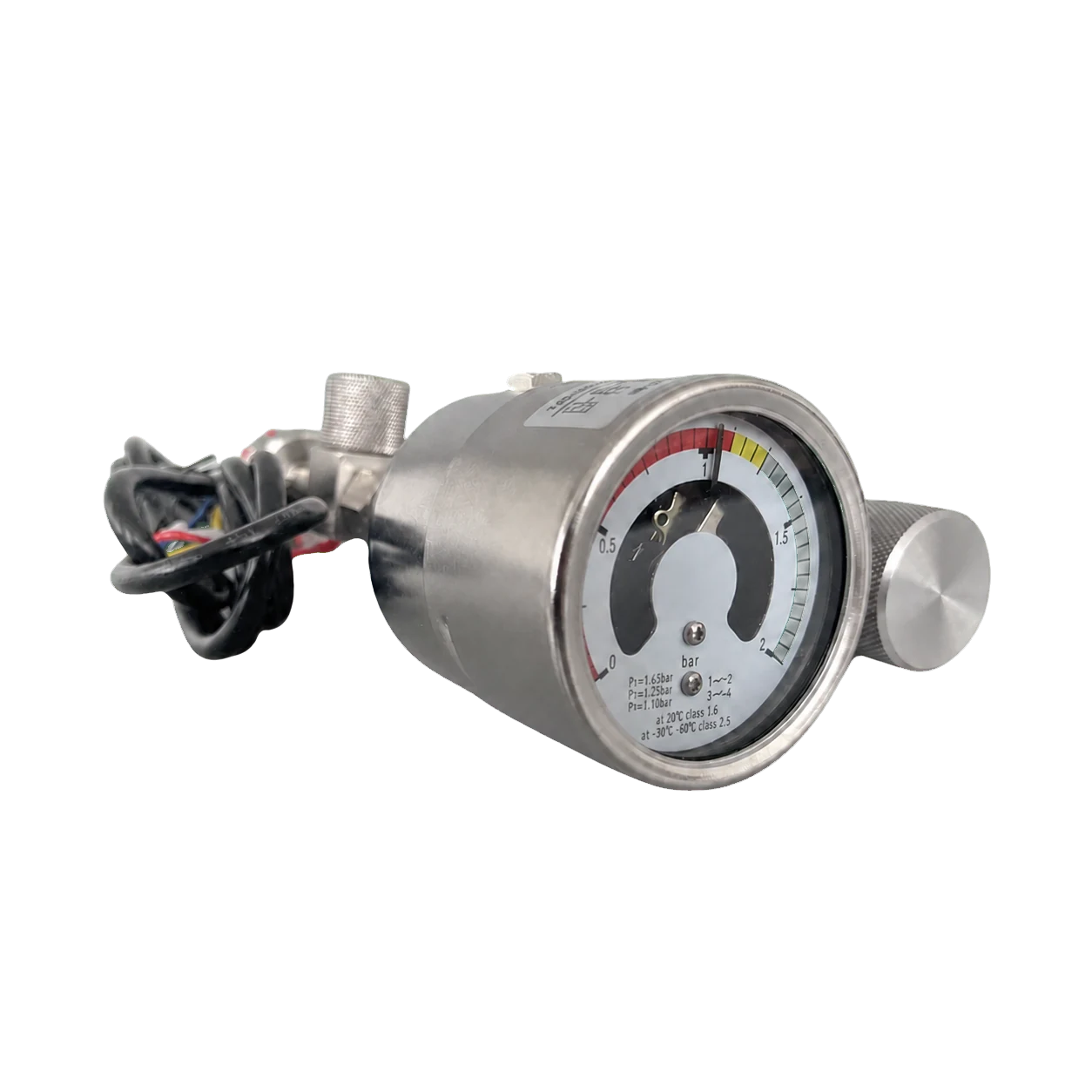
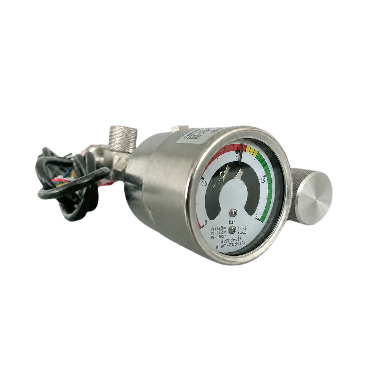
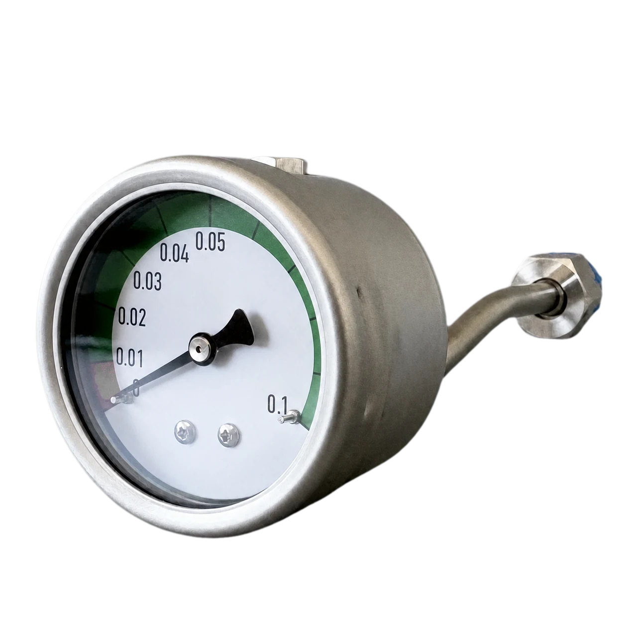
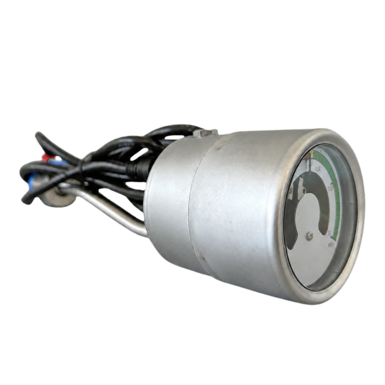
SF6 Gas Density Monitor for GIS and RMU

Select an SF6 gas density monitor for GIS and RMU gas compartments. Compare V2-103 data, dial and scale, mounting thread, alarm and lockout contacts, connection interface and RFQ inputs.

Technical review

V2-103 Technical Data & Drawing

Compare the published V2-103 parameters with the interface drawing, then confirm dial, scale, mounting, process thread, alarm and lockout settings for the GIS or RMU project.

V2-103 SF6 gas density monitorSeries configuration options
Selection parameter Configuration
Product series V2-103 SF6 gas density monitor
Nominal dial and scale configuration 100 mm; -0.1 to 0.9 MPa
Available dial diameters 63, 80, 100, 125, 160, 200 and 250 mm
Standards EN 837-1; ASME B40.1
Documentation and marking ISO 9001; CE; KS
Case material Stainless steel 316
Lens Tempered glass / safety glass
Dial plate Aluminum
Sensing element and connection Stainless steel
Mounting options Bottom type or back type
Thread options 1/2 PT; 1/2 NPT; 1/2 G (BSP); M20 x 1.5; project-specific options
Scale options -1 to 1000 bar on request; psi, kg/cm2, MPa, kPa, mmH2O or mbar
Case filling Glycerin, silicone or dry
Ingress protection IP65
Accuracy 1.6% for 63/80 mm; 1.0% for 100/125/160/200/250 mm

Engineering selection inputs

Prepare Monitor Project Inputs

Confirm the gas medium, dial and scale, alarm and lockout contacts, mounting, process connection and electrical interface against the GIS or RMU project before quotation.

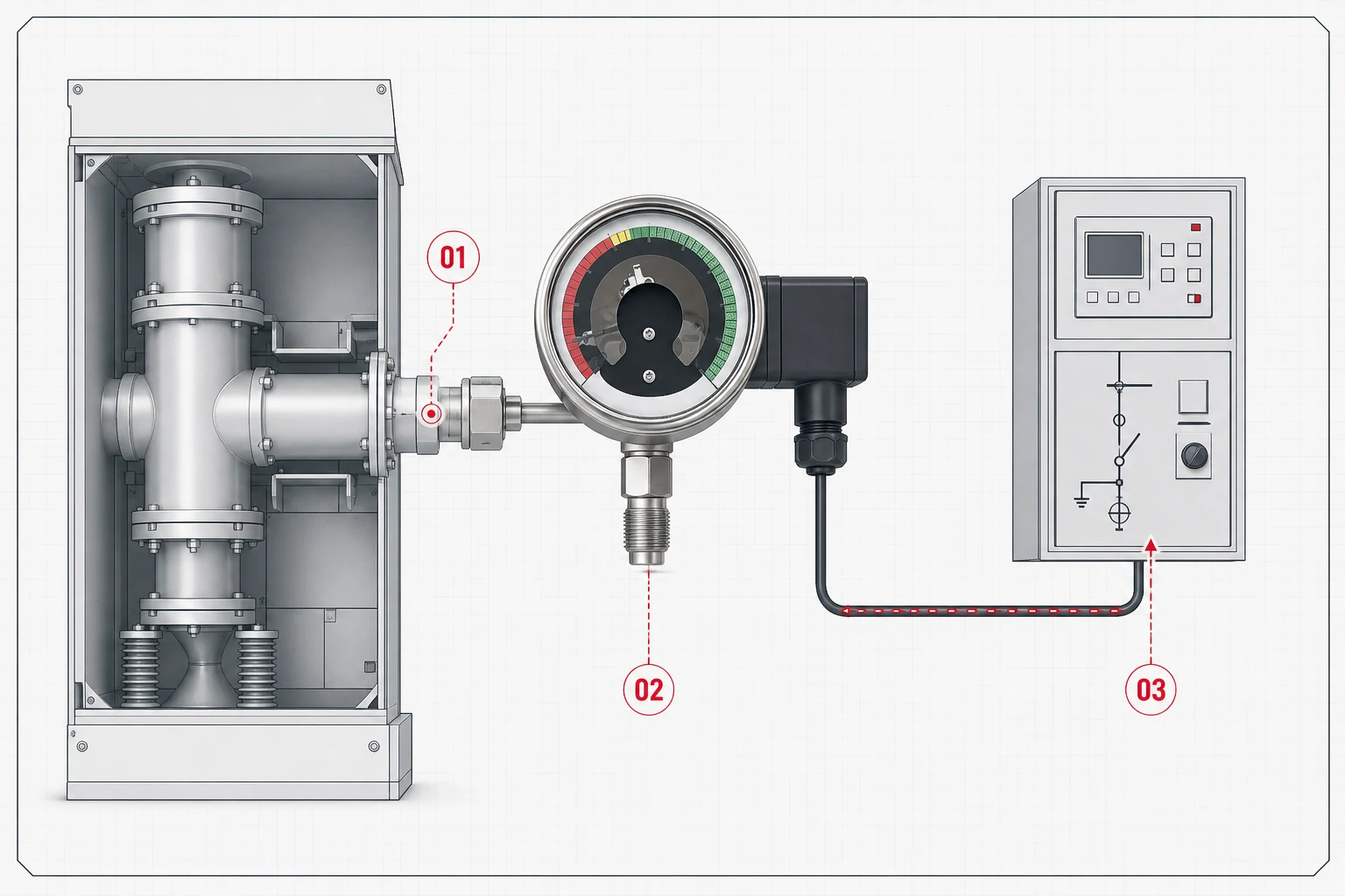
GIS and RMU SF6 gas density monitor interface diagram

Bring the correct engineering inputs into one review.

Gas compartment and monitoring duty

Specify SF6 or the selected gas medium, rated filling condition, reference temperature, indication role and alarm or lockout duty.

Mounting and connection interface

Provide mounting direction, process thread, sealing arrangement, available clearance, connector or cable direction and interface drawing.

Alarm, lockout and electrical contacts

Define set points, contact form, electrical rating, reset logic, connector pinout and coordination with the protection circuit.

Configuration and marking

Define dial color zones, scale units, nameplate, language, logo and any non-standard mounting or connection requirements.

Inspection and documentation

State calibration, leak-tightness, contact-operation, material, traceability and inspection-document requirements.

Packing and delivery

State quantity, spare ratio, destination, packing method, logistics constraints and requested delivery timing.

Project review workflow

Project Review to Delivery

Follow six connected checks from monitoring duty and interface review through documentation, packing and delivery.

  1. 01

    Gas and monitoring duty

    Define the gas medium, reference filling condition, indication role and alarm or lockout requirement.

  2. 02

    Dial and scale selection

    Select dial diameter, scale range and units, accuracy requirement, mounting direction and viewing position.

  3. 03

    Alarm and lockout logic

    Set contact form, thresholds, reset behavior, electrical rating and protection-circuit coordination.

  4. 04

    Mechanical and electrical interface

    Confirm process thread, sealing, connector or cable direction, pinout, envelope and available clearance.

  5. 05

    Drawing and document package

    Align the interface drawing, marking, inspection, calibration, contact-operation and traceability documents.

  6. 06

    Packing and delivery

    Confirm quantity, spare ratio, packing method, destination, consignee details and required schedule.

Technical FAQ

SF6 Gas Density Monitor FAQ

Engineering and procurement guidance for V2-103 selection, alarm and lockout contacts, mounting and GIS/RMU interface requirements.

What does an SF6 gas density monitor do in GIS or RMU switchgear?

It provides local gas-density or pressure indication and can support alarm and lockout contact functions for the gas compartment. The selected scale, compensation basis, contact logic and set points must match the switchgear protection scheme.

What information is needed to select a V2-103 density monitor?

Provide the gas medium, reference filling condition, required dial diameter and scale, mounting direction, process thread, alarm and lockout set points, contact form and rating, connector or cable arrangement, quantity and destination.

How are alarm and lockout contacts specified?

Define the number of contacts, normally open or normally closed logic, alarm and lockout thresholds, reset behavior, electrical rating, connector pinout and coordination with the control or protection circuit.

Which installation details should accompany an SF6 density monitor RFQ?

Send the gas-compartment interface drawing, available mounting clearance, thread and sealing arrangement, cable or connector direction, panel or RMU model, service conditions, required documents, quantity and delivery schedule.

Engineering quotation

Request an SF6 Monitor Quote

Send the gas duty, dial, contacts, mounting interface and delivery scope. We will review the configuration for a model-specific quotation.

Prepare these project inputs

Gas medium, reference filling condition and monitoring roleDial diameter, scale range, units and accuracyAlarm and lockout contacts, set points and electrical ratingProcess thread, sealing, mounting, connector and pinoutGIS/RMU interface drawing, nameplate, standards and documentsQuantity, spare ratio, destination, packing and schedule

Request quotation