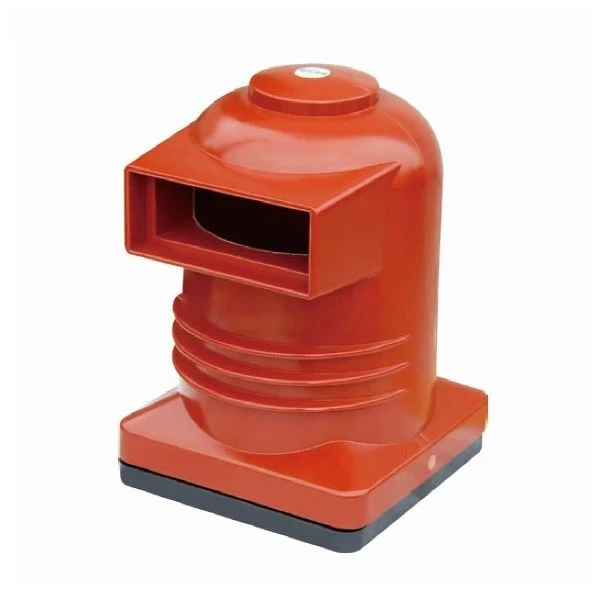
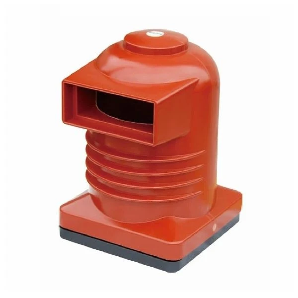
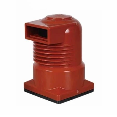
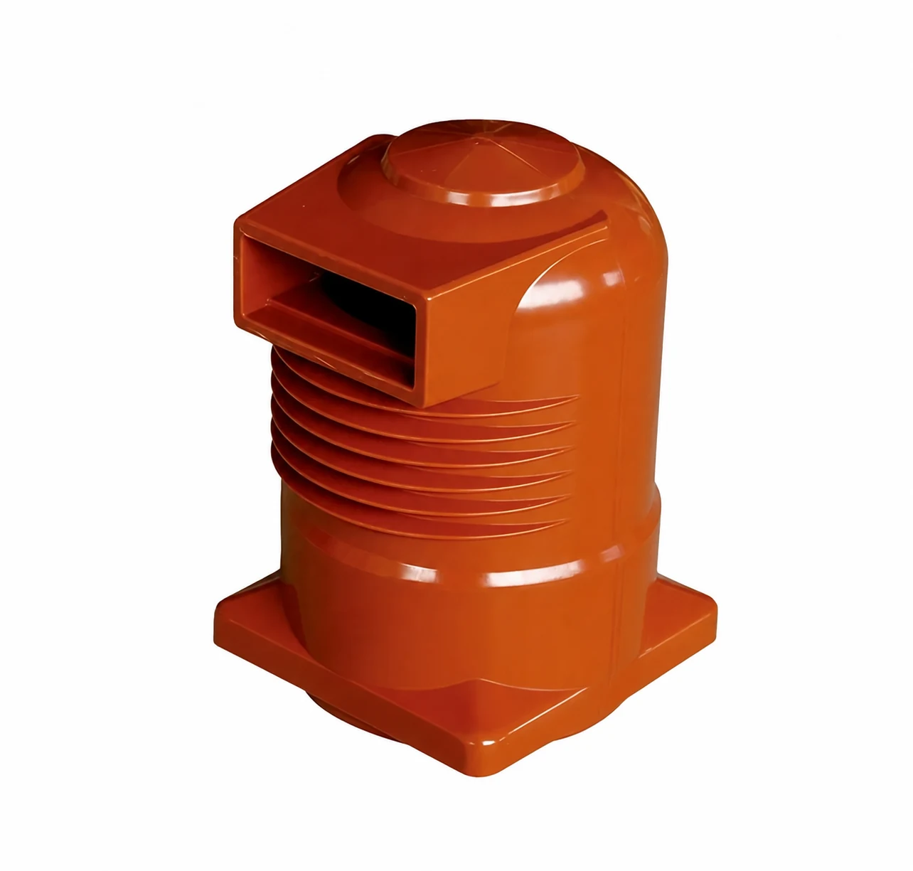
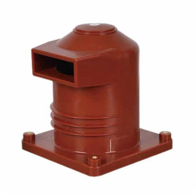
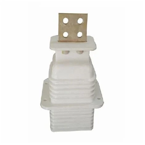
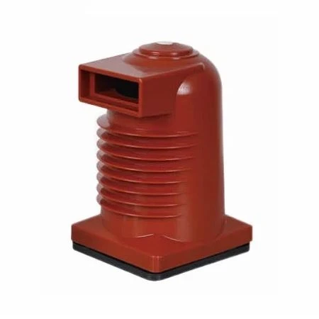
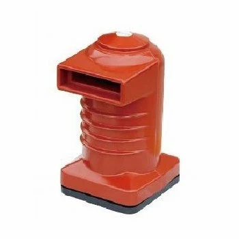
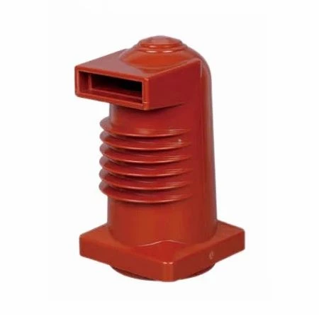
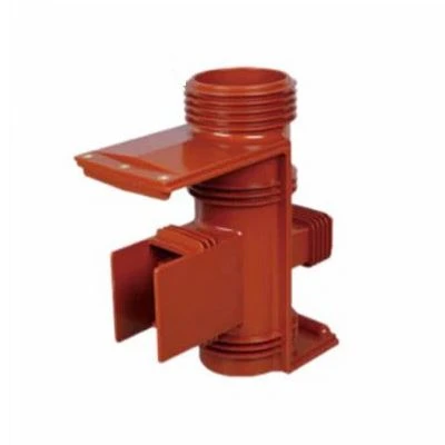
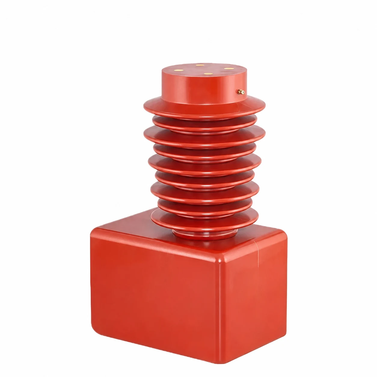
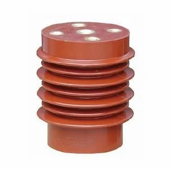
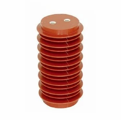
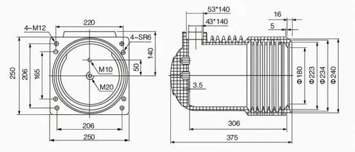
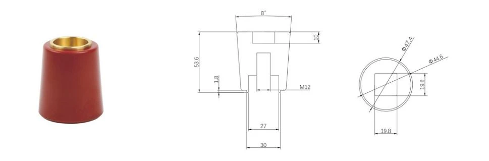
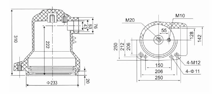
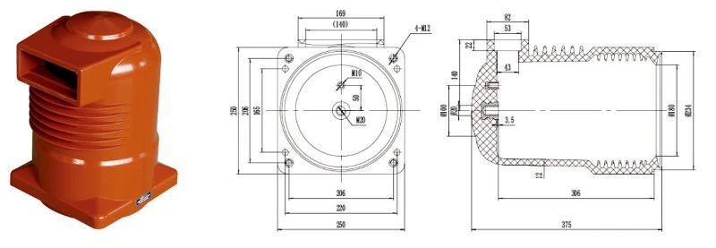
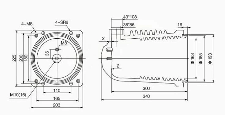
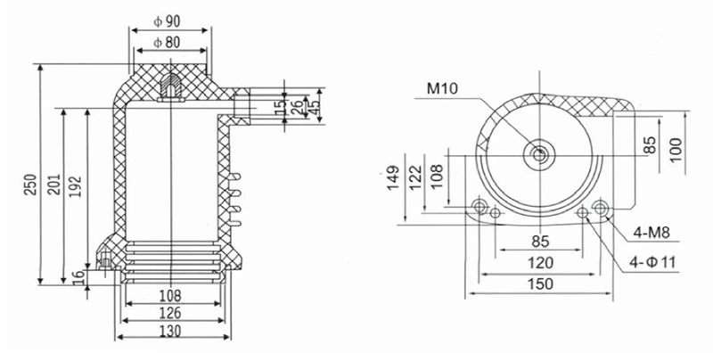
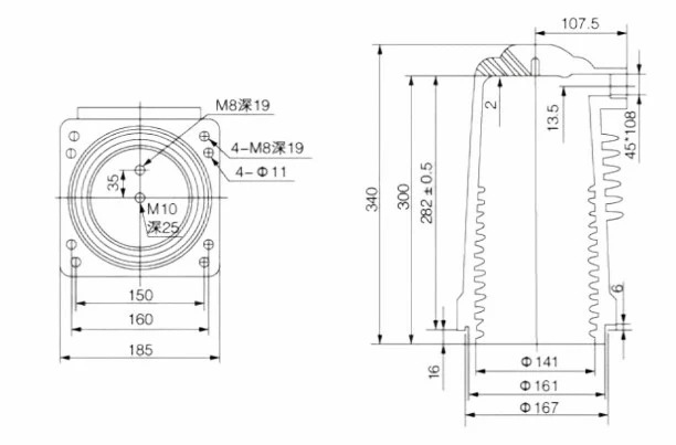
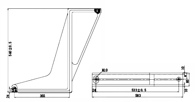
Send the request type, manufacturer, equipment model/year, part reference, ratings, quantity, destination, required date, and any drawing or photo notes. The SUVELL team will review the request.
Email: admin@suvell.com
Phone: +86 189 6871 1705
Factory: No.208 Wei 12 Rd, Yueqing Economic Development Zone, Wenzhou, Zhejiang, China
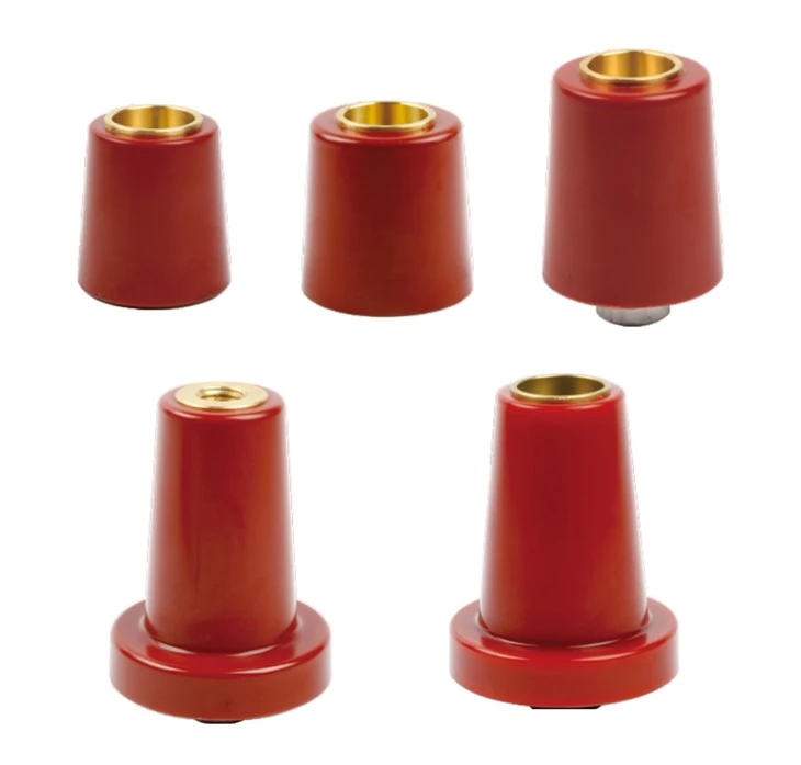
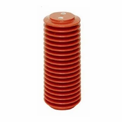
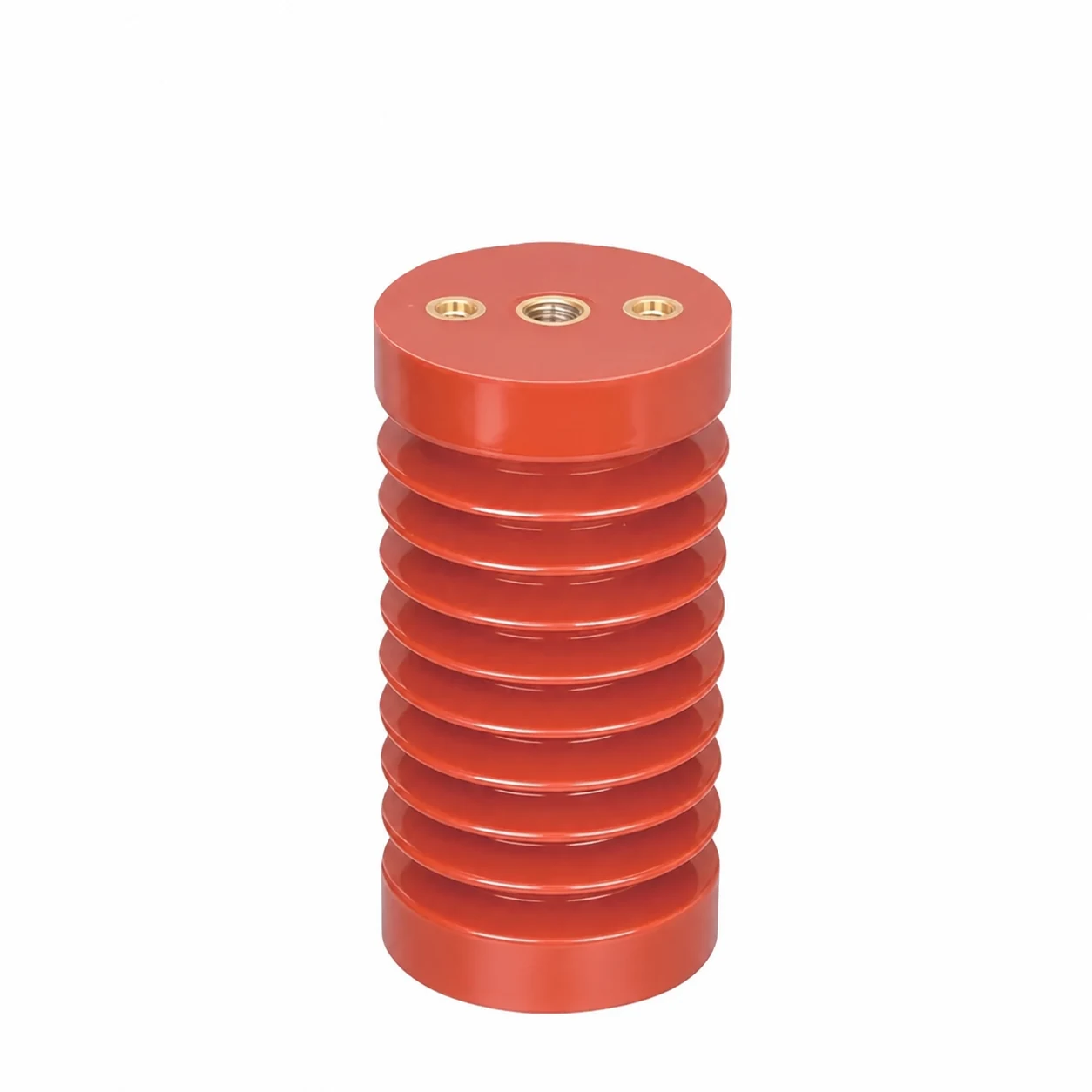
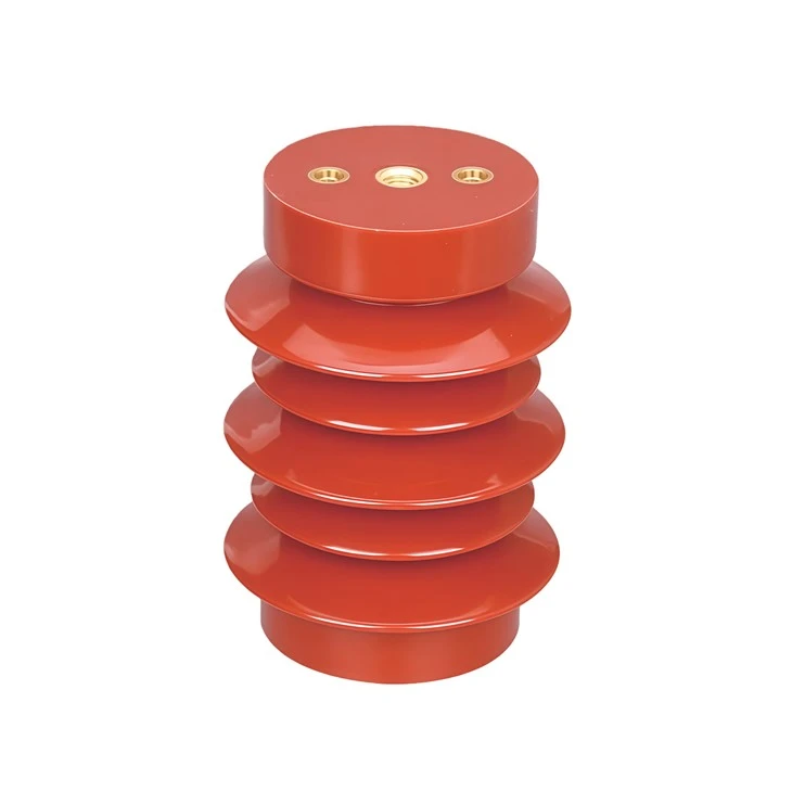
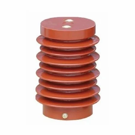
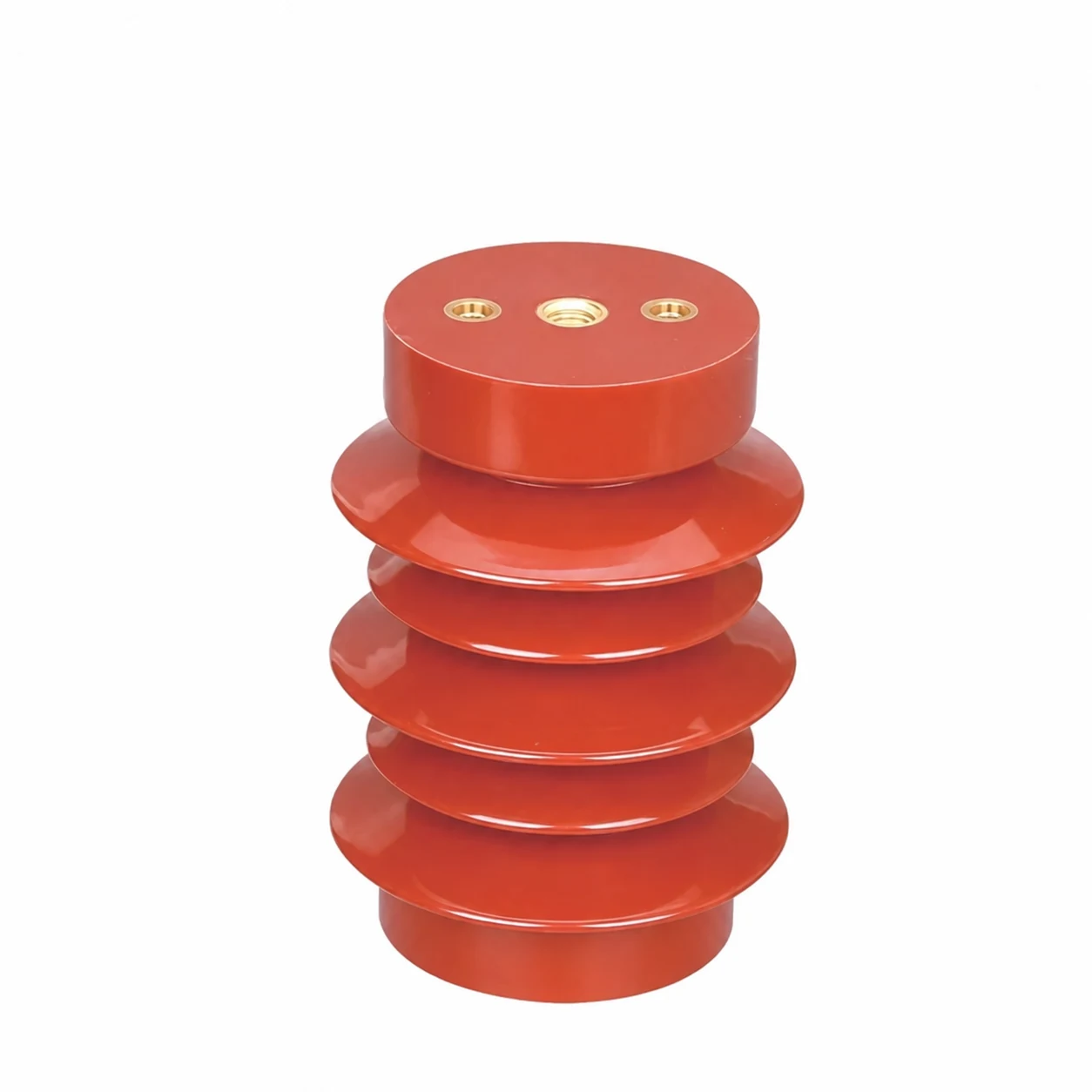
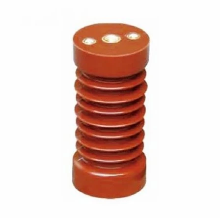
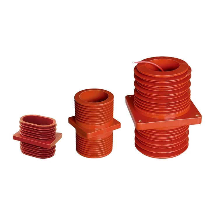
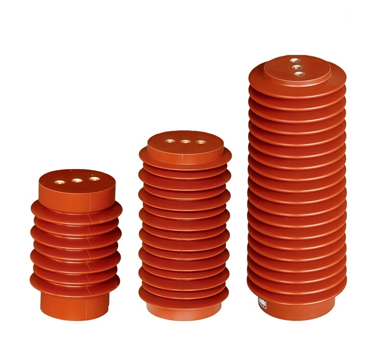
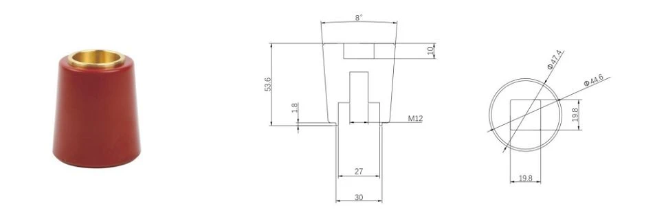
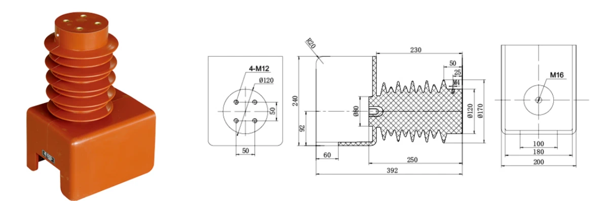
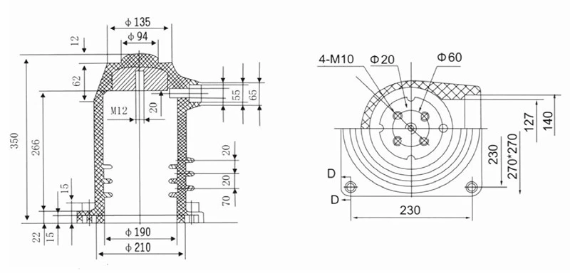
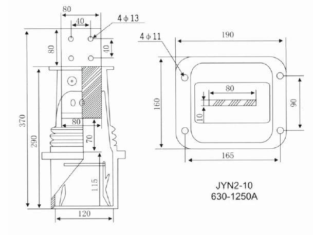
Compare epoxy resin insulators, bushings, contact boxes, sensors and mounting hardware for medium-voltage switchgear. Use the product drawings and selection inputs to prepare a model-specific RFQ.
Compare 39 component configurations across insulation, primary-contact, sensing and mounting functions. Open any card for its engineering selection inputs and interface drawing.
Insulator & bushing
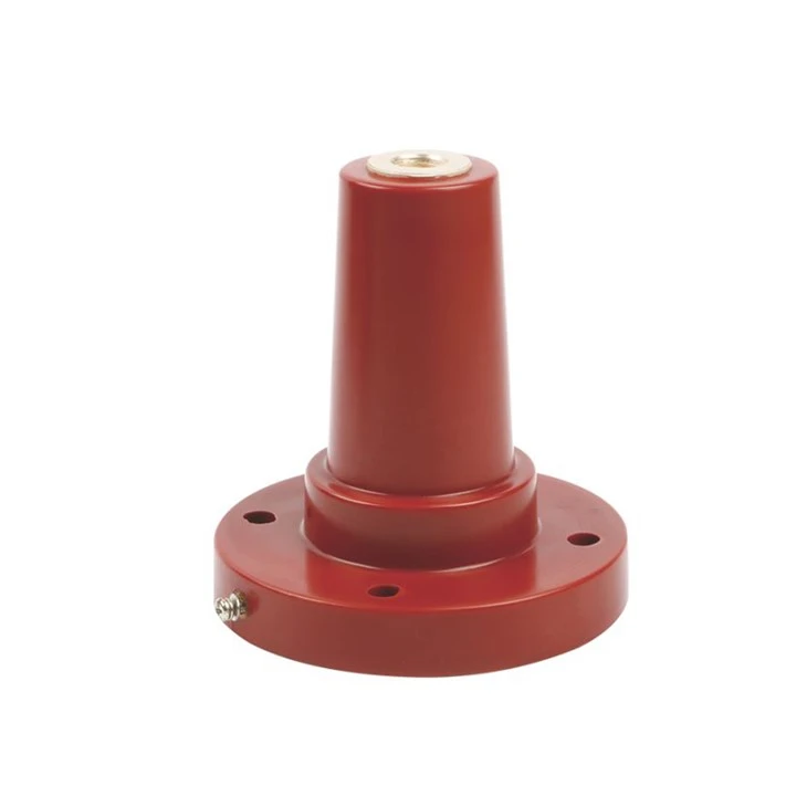
12 kV Epoxy Resin Insulator Plug
Compare insulation duty, conductor path, mounting geometry and switchgear clearances.
Review selection data
Insulator & bushing
15/25 kV Epoxy Resin Insulated Cable Cap
Compare insulation duty, conductor path, mounting geometry and switchgear clearances.
Review selection data
Insulator & bushing
24 kV Epoxy Resin Insulator Plug
Compare insulation duty, conductor path, mounting geometry and switchgear clearances.
Review selection data
Insulator & bushing
35 kV Epoxy Resin Insulator Plug
Compare insulation duty, conductor path, mounting geometry and switchgear clearances.
Review selection data
Insulator & bushing
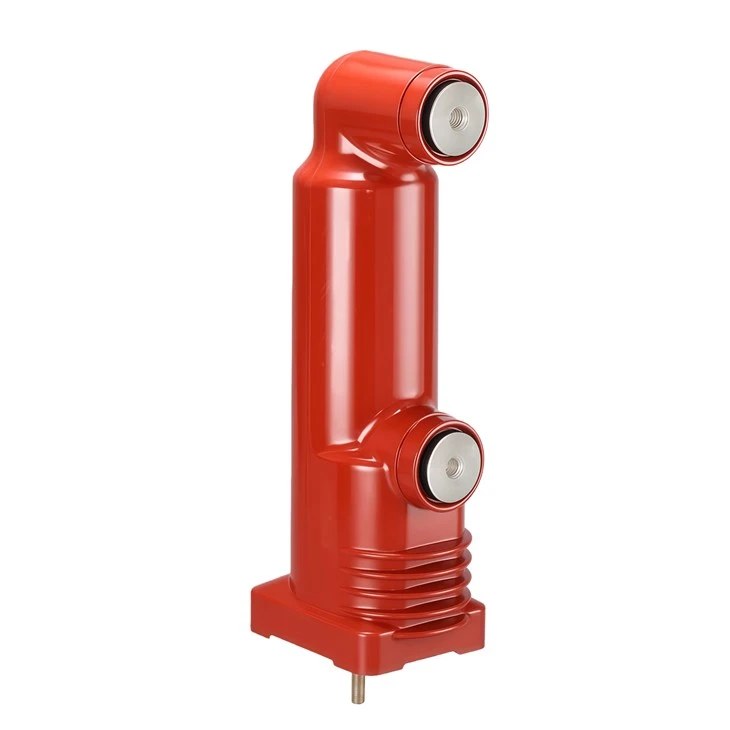
Epoxy Resin Cabinet Bushing for Vacuum Load Breaker
Compare insulation duty, conductor path, mounting geometry and switchgear clearances.
Review selection data
Insulator & bushing
Capacitive Epoxy Resin Support Insulator
Compare insulation duty, conductor path, mounting geometry and switchgear clearances.
Review selection data
Insulator & bushing
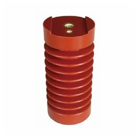
12 kV Epoxy Resin Support Insulator
Compare insulation duty, conductor path, mounting geometry and switchgear clearances.
Review selection data
Insulator & bushing
Handcart Support Insulator
Compare insulation duty, conductor path, mounting geometry and switchgear clearances.
Review selection data
Insulator & bushing
High-Voltage Epoxy Resin Switchgear Insulator
Compare insulation duty, conductor path, mounting geometry and switchgear clearances.
Review selection data
Insulator & bushing
12 kV High-Voltage Support Insulator
Compare insulation duty, conductor path, mounting geometry and switchgear clearances.
Review selection data
Insulator & bushing
High-Voltage Switchgear Insulator
Compare insulation duty, conductor path, mounting geometry and switchgear clearances.
Review selection data
Insulator & bushing
Indoor High-Voltage Epoxy Resin Insulator
Compare insulation duty, conductor path, mounting geometry and switchgear clearances.
Review selection data
Insulator & bushing
Switchgear Support and Busbar Insulators
Compare insulation duty, conductor path, mounting geometry and switchgear clearances.
Review selection data
Insulator & bushing
12/24/36 kV Epoxy Resin Through-Wall Bushing
Compare insulation duty, conductor path, mounting geometry and switchgear clearances.
Review selection data
Insulator & bushing
12/24/36 kV High-Voltage Epoxy Resin Insulator
Compare insulation duty, conductor path, mounting geometry and switchgear clearances.
Review selection data
Insulator & bushing
12 kV 630 A Single-Side Epoxy Resin Bushing (EU Type)
Compare insulation duty, conductor path, mounting geometry and switchgear clearances.
Review selection data
Insulator & bushing
12 kV Epoxy Resin Insulated Tube
Compare insulation duty, conductor path, mounting geometry and switchgear clearances.
Review selection data
Contact box
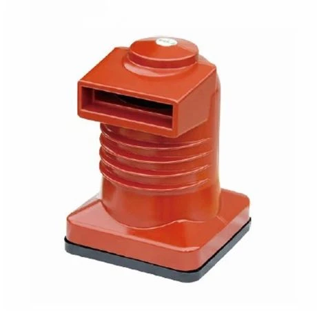
1250 A Epoxy Resin Insulating Contact Box
Compare current duty, primary contact interface, phase spacing and panel mounting.
Review selection data
Contact box
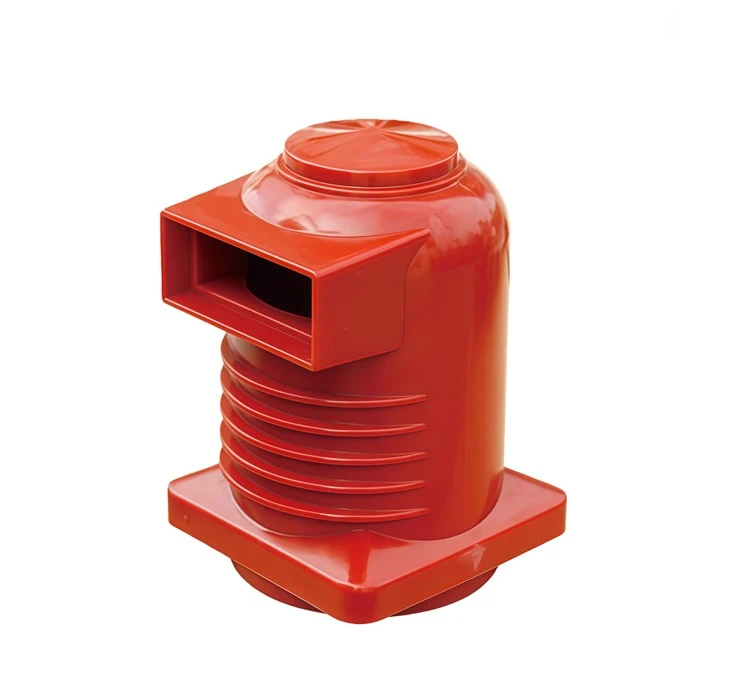
12 kV Epoxy Resin Insulating Contact Box
Compare current duty, primary contact interface, phase spacing and panel mounting.
Review selection data
Contact box
1600–2000 A Epoxy Resin Insulating Contact Box
Compare current duty, primary contact interface, phase spacing and panel mounting.
Review selection data
Contact box
1600 A Epoxy Resin Insulating Contact Box
Compare current duty, primary contact interface, phase spacing and panel mounting.
Review selection data
Contact box
2000–2500 A Epoxy Resin Insulating Contact Box
Compare current duty, primary contact interface, phase spacing and panel mounting.
Review selection data
Contact box
2500–3150 A Epoxy Resin Insulating Contact Box
Compare current duty, primary contact interface, phase spacing and panel mounting.
Review selection data
Contact box
24 kV Epoxy Resin Insulating Contact Box
Compare current duty, primary contact interface, phase spacing and panel mounting.
Review selection data
Contact box
4000 A Epoxy Resin Insulating Contact Box
Compare current duty, primary contact interface, phase spacing and panel mounting.
Review selection data
Contact box
630–1250 A Epoxy Resin Insulating Contact Box
Compare current duty, primary contact interface, phase spacing and panel mounting.
Review selection data
Contact box
630–1600 A Epoxy Resin Insulating Contact Box
Compare current duty, primary contact interface, phase spacing and panel mounting.
Review selection data
Contact box
630/1250 A Epoxy Resin Insulating Contact Box
Compare current duty, primary contact interface, phase spacing and panel mounting.
Review selection data
Contact box
630 A Epoxy Resin Insulating Contact Box
Compare current duty, primary contact interface, phase spacing and panel mounting.
Review selection data
Contact box
Insulating Contact Box for ABB Switchgear
Compare current duty, primary contact interface, phase spacing and panel mounting.
Review selection data
Contact box
36 kV Two-Way Shielded Epoxy Resin Contact Box
Compare current duty, primary contact interface, phase spacing and panel mounting.
Review selection data
Contact box
KYN61 Two-Way Shielded Insulating Contact Box
Compare current duty, primary contact interface, phase spacing and panel mounting.
Review selection data
Contact box
KYN61 Shielded Tee Insulating Contact Box
Compare current duty, primary contact interface, phase spacing and panel mounting.
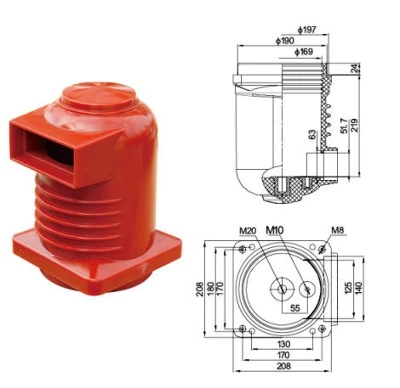
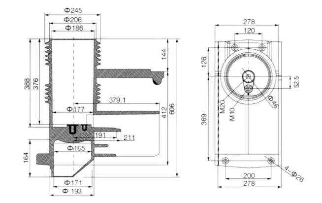
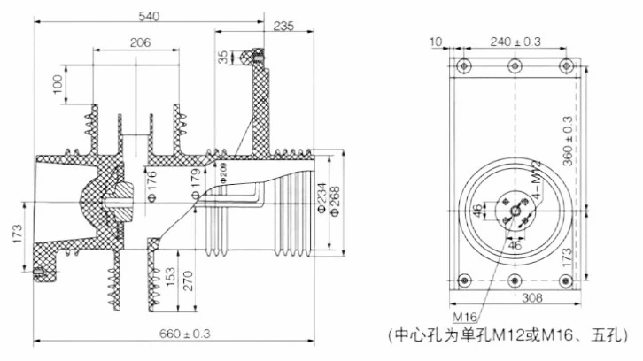
Use this 1250 A Epoxy Resin Insulating Contact Box configuration as the starting point, then align the electrical duty, insulation requirements and mechanical interface with the switchgear assembly.
Engineering selection inputs
Selection item
Project input
Application role
1250 A Epoxy Resin Insulating Contact Box for the switchgear primary contact and insulation interface
Voltage and current duty
Initial product scope: 1250 A; include system voltage, continuous current, conductor size and temperature-rise conditions
Primary contact interface
Specify fixed or moving contact arrangement, conductor orientation, contact diameter and connection details
Insulation and phase layout
Provide phase spacing, clearance envelope, earthing or shielding arrangement and indoor service conditions
Mechanical interface
Provide panel mounting face, hole centers, overall envelope, busbar route and adjacent-component clearances
RFQ inputs
Reference 1250 A Epoxy Resin Insulating Contact Box; attach the panel GA or interface drawing, quantity, destination, standards and delivery schedule
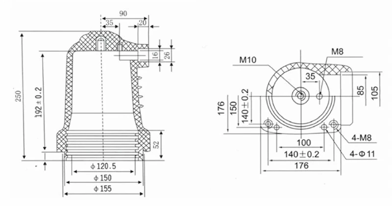
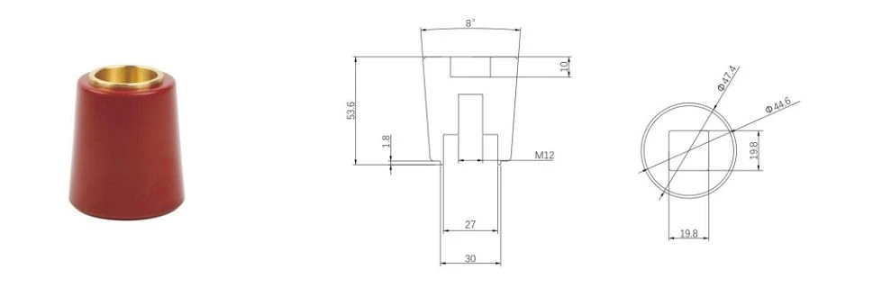
Interface drawing
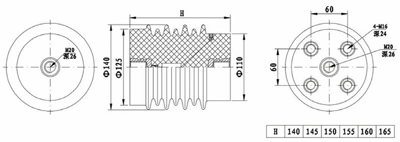
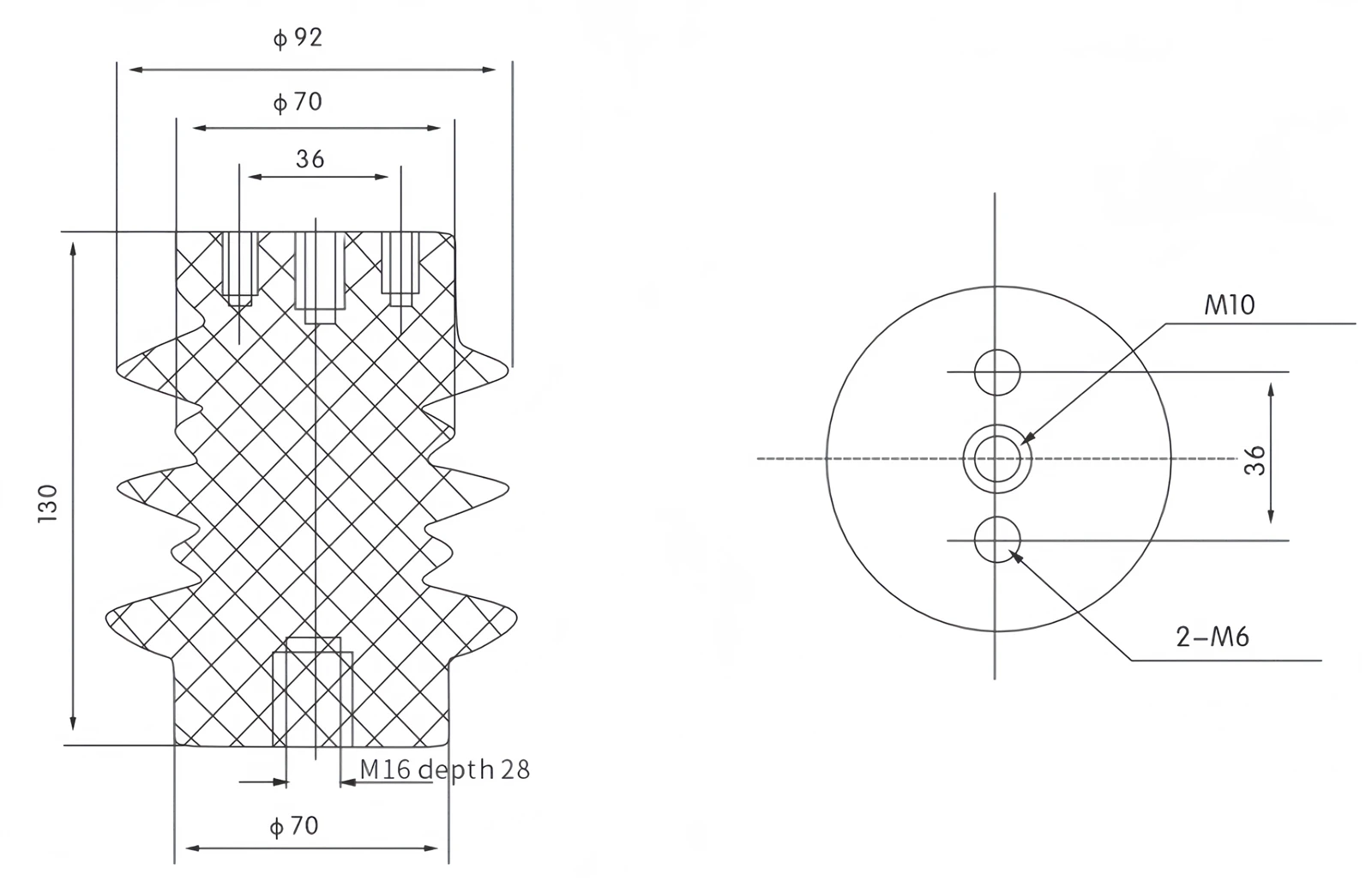
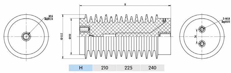
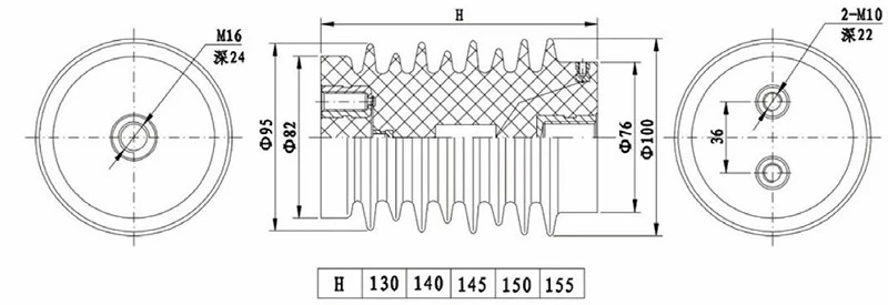
Open the full-size drawing to compare the component envelope, mounting points and switchgear interface.
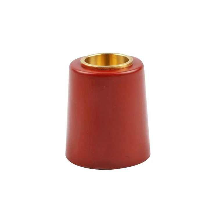
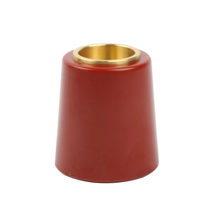
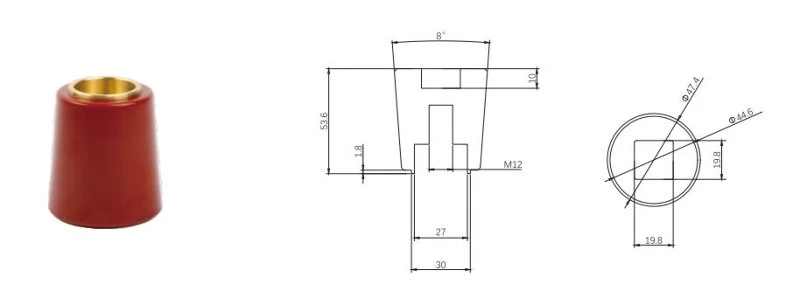
Use this 12 kV Epoxy Resin Insulator Plug configuration as the starting point, then align the electrical duty, insulation requirements and mechanical interface with the switchgear assembly.
Engineering selection inputs
Selection item
Project input
Application role
12 kV Epoxy Resin Insulator Plug for insulation, conductor support or a switchgear connection interface
Voltage and current scope
Initial product scope: 12 kV; include system voltage, insulation level and conductor or current duty
Insulation coordination
Specify creepage, clearance, pollution conditions, altitude, temperature and indoor or outdoor service
Conductor interface
Provide busbar, contact, cable or embedded-conductor geometry, orientation and connection details
Mechanical interface
Provide mounting face, hole centers, overall envelope, sealing arrangement and adjacent clearances
RFQ inputs
Reference 12 kV Epoxy Resin Insulator Plug; attach the interface drawing, quantity, destination, standards and delivery schedule
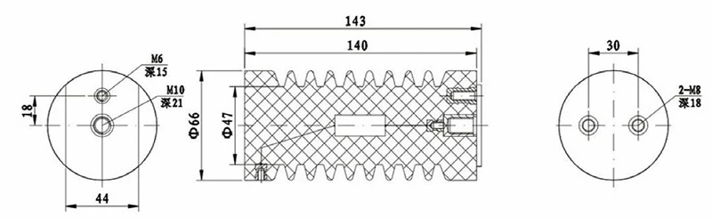
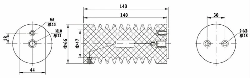
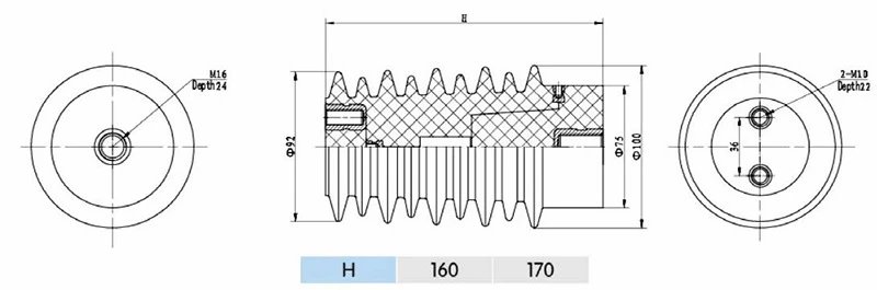
Interface drawing
Open the full-size drawing to compare the component envelope, mounting points and switchgear interface.
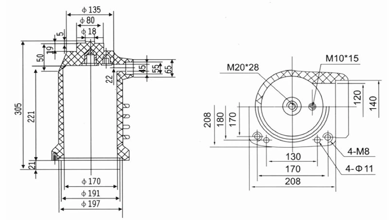
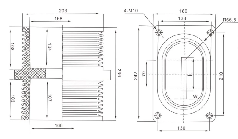
Use this 12 kV Epoxy Resin Insulating Contact Box configuration as the starting point, then align the electrical duty, insulation requirements and mechanical interface with the switchgear assembly.
Engineering selection inputs
Selection item
Project input
Application role
12 kV Epoxy Resin Insulating Contact Box for the switchgear primary contact and insulation interface
Voltage and current duty
Initial product scope: 12 kV; include system voltage, continuous current, conductor size and temperature-rise conditions
Primary contact interface
Specify fixed or moving contact arrangement, conductor orientation, contact diameter and connection details
Insulation and phase layout
Provide phase spacing, clearance envelope, earthing or shielding arrangement and indoor service conditions
Mechanical interface
Provide panel mounting face, hole centers, overall envelope, busbar route and adjacent-component clearances
RFQ inputs
Reference 12 kV Epoxy Resin Insulating Contact Box; attach the panel GA or interface drawing, quantity, destination, standards and delivery schedule
Interface drawing
Open the full-size drawing to compare the component envelope, mounting points and switchgear interface.
Use this 15/25 kV Epoxy Resin Insulated Cable Cap configuration as the starting point, then align the electrical duty, insulation requirements and mechanical interface with the switchgear assembly.
Engineering selection inputs
Selection item
Project input
Application role
15/25 kV Epoxy Resin Insulated Cable Cap for insulation, conductor support or a switchgear connection interface
Voltage and current scope
Initial product scope: 15/25 kV; include system voltage, insulation level and conductor or current duty
Insulation coordination
Specify creepage, clearance, pollution conditions, altitude, temperature and indoor or outdoor service
Conductor interface
Provide busbar, contact, cable or embedded-conductor geometry, orientation and connection details
Mechanical interface
Provide mounting face, hole centers, overall envelope, sealing arrangement and adjacent clearances
RFQ inputs
Reference 15/25 kV Epoxy Resin Insulated Cable Cap; attach the interface drawing, quantity, destination, standards and delivery schedule
Interface drawing
Open the full-size drawing to compare the component envelope, mounting points and switchgear interface.
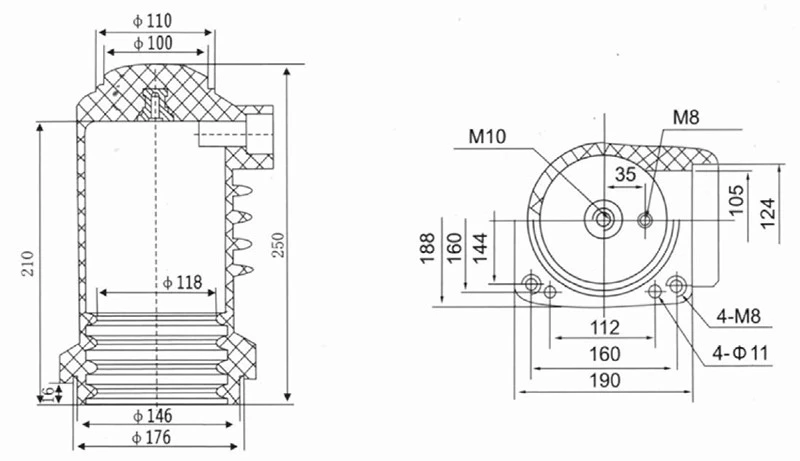
Use this 1600–2000 A Epoxy Resin Insulating Contact Box configuration as the starting point, then align the electrical duty, insulation requirements and mechanical interface with the switchgear assembly.
Engineering selection inputs
Selection item
Project input
Application role
1600–2000 A Epoxy Resin Insulating Contact Box for the switchgear primary contact and insulation interface
Voltage and current duty
Initial product scope: 1600–2000 A; include system voltage, continuous current, conductor size and temperature-rise conditions
Primary contact interface
Specify fixed or moving contact arrangement, conductor orientation, contact diameter and connection details
Insulation and phase layout
Provide phase spacing, clearance envelope, earthing or shielding arrangement and indoor service conditions
Mechanical interface
Provide panel mounting face, hole centers, overall envelope, busbar route and adjacent-component clearances
RFQ inputs
Reference 1600–2000 A Epoxy Resin Insulating Contact Box; attach the panel GA or interface drawing, quantity, destination, standards and delivery schedule
Interface drawing
Open the full-size drawing to compare the component envelope, mounting points and switchgear interface.
Use this 1600 A Epoxy Resin Insulating Contact Box configuration as the starting point, then align the electrical duty, insulation requirements and mechanical interface with the switchgear assembly.
Engineering selection inputs
Selection item
Project input
Application role
1600 A Epoxy Resin Insulating Contact Box for the switchgear primary contact and insulation interface
Voltage and current duty
Initial product scope: 1600 A; include system voltage, continuous current, conductor size and temperature-rise conditions
Primary contact interface
Specify fixed or moving contact arrangement, conductor orientation, contact diameter and connection details
Insulation and phase layout
Provide phase spacing, clearance envelope, earthing or shielding arrangement and indoor service conditions
Mechanical interface
Provide panel mounting face, hole centers, overall envelope, busbar route and adjacent-component clearances
RFQ inputs
Reference 1600 A Epoxy Resin Insulating Contact Box; attach the panel GA or interface drawing, quantity, destination, standards and delivery schedule
Interface drawing
Open the full-size drawing to compare the component envelope, mounting points and switchgear interface.
Use this 2000–2500 A Epoxy Resin Insulating Contact Box configuration as the starting point, then align the electrical duty, insulation requirements and mechanical interface with the switchgear assembly.
Engineering selection inputs
Selection item
Project input
Application role
2000–2500 A Epoxy Resin Insulating Contact Box for the switchgear primary contact and insulation interface
Voltage and current duty
Initial product scope: 2000–2500 A; include system voltage, continuous current, conductor size and temperature-rise conditions
Primary contact interface
Specify fixed or moving contact arrangement, conductor orientation, contact diameter and connection details
Insulation and phase layout
Provide phase spacing, clearance envelope, earthing or shielding arrangement and indoor service conditions
Mechanical interface
Provide panel mounting face, hole centers, overall envelope, busbar route and adjacent-component clearances
RFQ inputs
Reference 2000–2500 A Epoxy Resin Insulating Contact Box; attach the panel GA or interface drawing, quantity, destination, standards and delivery schedule
Interface drawing
Open the full-size drawing to compare the component envelope, mounting points and switchgear interface.
Use this 24 kV Epoxy Resin Insulator Plug configuration as the starting point, then align the electrical duty, insulation requirements and mechanical interface with the switchgear assembly.
Engineering selection inputs
Selection item
Project input
Application role
24 kV Epoxy Resin Insulator Plug for insulation, conductor support or a switchgear connection interface
Voltage and current scope
Initial product scope: 24 kV; include system voltage, insulation level and conductor or current duty
Insulation coordination
Specify creepage, clearance, pollution conditions, altitude, temperature and indoor or outdoor service
Conductor interface
Provide busbar, contact, cable or embedded-conductor geometry, orientation and connection details
Mechanical interface
Provide mounting face, hole centers, overall envelope, sealing arrangement and adjacent clearances
RFQ inputs
Reference 24 kV Epoxy Resin Insulator Plug; attach the interface drawing, quantity, destination, standards and delivery schedule
Interface drawing
Open the full-size drawing to compare the component envelope, mounting points and switchgear interface.
Use this 2500–3150 A Epoxy Resin Insulating Contact Box configuration as the starting point, then align the electrical duty, insulation requirements and mechanical interface with the switchgear assembly.
Engineering selection inputs
Selection item
Project input
Application role
2500–3150 A Epoxy Resin Insulating Contact Box for the switchgear primary contact and insulation interface
Voltage and current duty
Initial product scope: 2500–3150 A; include system voltage, continuous current, conductor size and temperature-rise conditions
Primary contact interface
Specify fixed or moving contact arrangement, conductor orientation, contact diameter and connection details
Insulation and phase layout
Provide phase spacing, clearance envelope, earthing or shielding arrangement and indoor service conditions
Mechanical interface
Provide panel mounting face, hole centers, overall envelope, busbar route and adjacent-component clearances
RFQ inputs
Reference 2500–3150 A Epoxy Resin Insulating Contact Box; attach the panel GA or interface drawing, quantity, destination, standards and delivery schedule
Interface drawing
Open the full-size drawing to compare the component envelope, mounting points and switchgear interface.
Use this 24 kV Epoxy Resin Insulating Contact Box configuration as the starting point, then align the electrical duty, insulation requirements and mechanical interface with the switchgear assembly.
Engineering selection inputs
Selection item
Project input
Application role
24 kV Epoxy Resin Insulating Contact Box for the switchgear primary contact and insulation interface
Voltage and current duty
Initial product scope: 24 kV; include system voltage, continuous current, conductor size and temperature-rise conditions
Primary contact interface
Specify fixed or moving contact arrangement, conductor orientation, contact diameter and connection details
Insulation and phase layout
Provide phase spacing, clearance envelope, earthing or shielding arrangement and indoor service conditions
Mechanical interface
Provide panel mounting face, hole centers, overall envelope, busbar route and adjacent-component clearances
RFQ inputs
Reference 24 kV Epoxy Resin Insulating Contact Box; attach the panel GA or interface drawing, quantity, destination, standards and delivery schedule
Interface drawing
Open the full-size drawing to compare the component envelope, mounting points and switchgear interface.
Use this 35 kV Epoxy Resin Insulator Plug configuration as the starting point, then align the electrical duty, insulation requirements and mechanical interface with the switchgear assembly.
Engineering selection inputs
Selection item
Project input
Application role
35 kV Epoxy Resin Insulator Plug for insulation, conductor support or a switchgear connection interface
Voltage and current scope
Initial product scope: 35 kV; include system voltage, insulation level and conductor or current duty
Insulation coordination
Specify creepage, clearance, pollution conditions, altitude, temperature and indoor or outdoor service
Conductor interface
Provide busbar, contact, cable or embedded-conductor geometry, orientation and connection details
Mechanical interface
Provide mounting face, hole centers, overall envelope, sealing arrangement and adjacent clearances
RFQ inputs
Reference 35 kV Epoxy Resin Insulator Plug; attach the interface drawing, quantity, destination, standards and delivery schedule
Interface drawing
Open the full-size drawing to compare the component envelope, mounting points and switchgear interface.
Use this 36 kV Post Sensor for Switchgear configuration as the starting point, then align the electrical duty, insulation requirements and mechanical interface with the switchgear assembly.
Engineering selection inputs
Selection item
Project input
Application role
36 kV Post Sensor for Switchgear for measurement, indication, automation or protection within MV switchgear
Electrical scope
Initial product scope: 36 kV; define the measured quantity, primary system voltage and conductor duty
Signal and secondary interface
Specify ratio or output, accuracy requirement, burden, terminal arrangement and connected device
Primary conductor and insulation
Provide the conductor route, insulation level, shielding or earthing method and service environment
Mechanical interface
Provide mounting position, hole pattern, component envelope, terminal access and panel clearances
RFQ inputs
Reference 36 kV Post Sensor for Switchgear; attach the SLD, panel drawing, signal requirement, quantity, destination and schedule
Interface drawing
Open the full-size drawing to compare the component envelope, mounting points and switchgear interface.
Use this 4000 A Epoxy Resin Insulating Contact Box configuration as the starting point, then align the electrical duty, insulation requirements and mechanical interface with the switchgear assembly.
Engineering selection inputs
Selection item
Project input
Application role
4000 A Epoxy Resin Insulating Contact Box for the switchgear primary contact and insulation interface
Voltage and current duty
Initial product scope: 4000 A; include system voltage, continuous current, conductor size and temperature-rise conditions
Primary contact interface
Specify fixed or moving contact arrangement, conductor orientation, contact diameter and connection details
Insulation and phase layout
Provide phase spacing, clearance envelope, earthing or shielding arrangement and indoor service conditions
Mechanical interface
Provide panel mounting face, hole centers, overall envelope, busbar route and adjacent-component clearances
RFQ inputs
Reference 4000 A Epoxy Resin Insulating Contact Box; attach the panel GA or interface drawing, quantity, destination, standards and delivery schedule
Interface drawing
Open the full-size drawing to compare the component envelope, mounting points and switchgear interface.
Use this 630–1250 A Epoxy Resin Insulating Contact Box configuration as the starting point, then align the electrical duty, insulation requirements and mechanical interface with the switchgear assembly.
Engineering selection inputs
Selection item
Project input
Application role
630–1250 A Epoxy Resin Insulating Contact Box for the switchgear primary contact and insulation interface
Voltage and current duty
Initial product scope: 630–1250 A; include system voltage, continuous current, conductor size and temperature-rise conditions
Primary contact interface
Specify fixed or moving contact arrangement, conductor orientation, contact diameter and connection details
Insulation and phase layout
Provide phase spacing, clearance envelope, earthing or shielding arrangement and indoor service conditions
Mechanical interface
Provide panel mounting face, hole centers, overall envelope, busbar route and adjacent-component clearances
RFQ inputs
Reference 630–1250 A Epoxy Resin Insulating Contact Box; attach the panel GA or interface drawing, quantity, destination, standards and delivery schedule
Interface drawing
Open the full-size drawing to compare the component envelope, mounting points and switchgear interface.
Use this 630–1600 A Epoxy Resin Insulating Contact Box configuration as the starting point, then align the electrical duty, insulation requirements and mechanical interface with the switchgear assembly.
Engineering selection inputs
Selection item
Project input
Application role
630–1600 A Epoxy Resin Insulating Contact Box for the switchgear primary contact and insulation interface
Voltage and current duty
Initial product scope: 630–1600 A; include system voltage, continuous current, conductor size and temperature-rise conditions
Primary contact interface
Specify fixed or moving contact arrangement, conductor orientation, contact diameter and connection details
Insulation and phase layout
Provide phase spacing, clearance envelope, earthing or shielding arrangement and indoor service conditions
Mechanical interface
Provide panel mounting face, hole centers, overall envelope, busbar route and adjacent-component clearances
RFQ inputs
Reference 630–1600 A Epoxy Resin Insulating Contact Box; attach the panel GA or interface drawing, quantity, destination, standards and delivery schedule
Interface drawing
Open the full-size drawing to compare the component envelope, mounting points and switchgear interface.
Use this 630/1250 A Epoxy Resin Insulating Contact Box configuration as the starting point, then align the electrical duty, insulation requirements and mechanical interface with the switchgear assembly.
Engineering selection inputs
Selection item
Project input
Application role
630/1250 A Epoxy Resin Insulating Contact Box for the switchgear primary contact and insulation interface
Voltage and current duty
Initial product scope: 630/1250 A; include system voltage, continuous current, conductor size and temperature-rise conditions
Primary contact interface
Specify fixed or moving contact arrangement, conductor orientation, contact diameter and connection details
Insulation and phase layout
Provide phase spacing, clearance envelope, earthing or shielding arrangement and indoor service conditions
Mechanical interface
Provide panel mounting face, hole centers, overall envelope, busbar route and adjacent-component clearances
RFQ inputs
Reference 630/1250 A Epoxy Resin Insulating Contact Box; attach the panel GA or interface drawing, quantity, destination, standards and delivery schedule
Interface drawing
Open the full-size drawing to compare the component envelope, mounting points and switchgear interface.
Use this 630 A Epoxy Resin Insulating Contact Box configuration as the starting point, then align the electrical duty, insulation requirements and mechanical interface with the switchgear assembly.
Engineering selection inputs
Selection item
Project input
Application role
630 A Epoxy Resin Insulating Contact Box for the switchgear primary contact and insulation interface
Voltage and current duty
Initial product scope: 630 A; include system voltage, continuous current, conductor size and temperature-rise conditions
Primary contact interface
Specify fixed or moving contact arrangement, conductor orientation, contact diameter and connection details
Insulation and phase layout
Provide phase spacing, clearance envelope, earthing or shielding arrangement and indoor service conditions
Mechanical interface
Provide panel mounting face, hole centers, overall envelope, busbar route and adjacent-component clearances
RFQ inputs
Reference 630 A Epoxy Resin Insulating Contact Box; attach the panel GA or interface drawing, quantity, destination, standards and delivery schedule
Interface drawing
Open the full-size drawing to compare the component envelope, mounting points and switchgear interface.
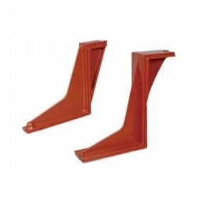
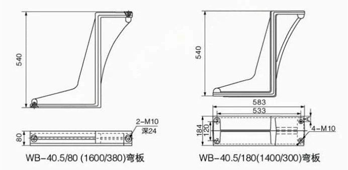
Use this Switchgear Bending Plate configuration as the starting point, then align the electrical duty, insulation requirements and mechanical interface with the switchgear assembly.
Engineering selection inputs
Selection item
Project input
Application role
Switchgear Bending Plate for switchgear component support, alignment or linkage mounting
Material and finish
Specify base material, thickness, surface treatment, corrosion conditions and marking requirements
Dimensions and holes
Provide overall dimensions, bend geometry, hole sizes, centers, tolerances and datum references
Mounting interface
Identify the panel, mechanism or insulation component interface and installation orientation
Mechanical duty
State the supported load, operating force, vibration conditions, clearances and fastening method
RFQ inputs
Reference Switchgear Bending Plate; attach the part or assembly drawing, quantity, finish, destination and schedule
Interface drawing
Open the full-size drawing to compare the component envelope, mounting points and switchgear interface.
Use this Insulating Contact Box for ABB Switchgear configuration as the starting point, then align the electrical duty, insulation requirements and mechanical interface with the switchgear assembly.
Engineering selection inputs
Selection item
Project input
Application role
Insulating Contact Box for ABB Switchgear for the switchgear primary contact and insulation interface
Voltage and current duty
Initial product scope: Define the system voltage and applicable current or mechanical duty; include system voltage, continuous current, conductor size and temperature-rise conditions
Primary contact interface
Specify fixed or moving contact arrangement, conductor orientation, contact diameter and connection details
Insulation and phase layout
Provide phase spacing, clearance envelope, earthing or shielding arrangement and indoor service conditions
Mechanical interface
Provide panel mounting face, hole centers, overall envelope, busbar route and adjacent-component clearances
RFQ inputs
Reference Insulating Contact Box for ABB Switchgear; attach the panel GA or interface drawing, quantity, destination, standards and delivery schedule
Interface drawing
Open the full-size drawing to compare the component envelope, mounting points and switchgear interface.
Use this KYN61 Switchgear Bending Plate configuration as the starting point, then align the electrical duty, insulation requirements and mechanical interface with the switchgear assembly.
Engineering selection inputs
Selection item
Project input
Application role
KYN61 Switchgear Bending Plate for switchgear component support, alignment or linkage mounting
Material and finish
Specify base material, thickness, surface treatment, corrosion conditions and marking requirements
Dimensions and holes
Provide overall dimensions, bend geometry, hole sizes, centers, tolerances and datum references
Mounting interface
Identify the panel, mechanism or insulation component interface and installation orientation
Mechanical duty
State the supported load, operating force, vibration conditions, clearances and fastening method
RFQ inputs
Reference KYN61 Switchgear Bending Plate; attach the part or assembly drawing, quantity, finish, destination and schedule
Interface drawing
Open the full-size drawing to compare the component envelope, mounting points and switchgear interface.
Epoxy Resin Cabinet Bushing for Vacuum Load Breaker
Use this Epoxy Resin Cabinet Bushing for Vacuum Load Breaker configuration as the starting point, then align the electrical duty, insulation requirements and mechanical interface with the switchgear assembly.
Engineering selection inputs
Selection item
Project input
Application role
Epoxy Resin Cabinet Bushing for Vacuum Load Breaker for insulation, conductor support or a switchgear connection interface
Voltage and current scope
Initial product scope: Define the system voltage and applicable current or mechanical duty; include system voltage, insulation level and conductor or current duty
Insulation coordination
Specify creepage, clearance, pollution conditions, altitude, temperature and indoor or outdoor service
Conductor interface
Provide busbar, contact, cable or embedded-conductor geometry, orientation and connection details
Mechanical interface
Provide mounting face, hole centers, overall envelope, sealing arrangement and adjacent clearances
RFQ inputs
Reference Epoxy Resin Cabinet Bushing for Vacuum Load Breaker; attach the interface drawing, quantity, destination, standards and delivery schedule
Interface drawing
Open the full-size drawing to compare the component envelope, mounting points and switchgear interface.
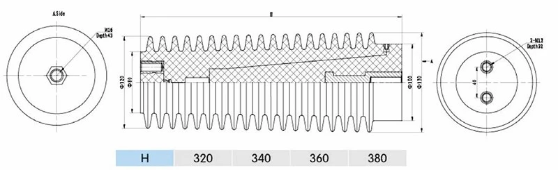
Use this Capacitive Epoxy Resin Support Insulator configuration as the starting point, then align the electrical duty, insulation requirements and mechanical interface with the switchgear assembly.
Engineering selection inputs
Selection item
Project input
Application role
Capacitive Epoxy Resin Support Insulator for insulation, conductor support or a switchgear connection interface
Voltage and current scope
Initial product scope: Define the system voltage and applicable current or mechanical duty; include system voltage, insulation level and conductor or current duty
Insulation coordination
Specify creepage, clearance, pollution conditions, altitude, temperature and indoor or outdoor service
Conductor interface
Provide busbar, contact, cable or embedded-conductor geometry, orientation and connection details
Mechanical interface
Provide mounting face, hole centers, overall envelope, sealing arrangement and adjacent clearances
RFQ inputs
Reference Capacitive Epoxy Resin Support Insulator; attach the interface drawing, quantity, destination, standards and delivery schedule
Interface drawing
Open the full-size drawing to compare the component envelope, mounting points and switchgear interface.
Use this Capacitive Epoxy Resin Sensor Insulator configuration as the starting point, then align the electrical duty, insulation requirements and mechanical interface with the switchgear assembly.
Engineering selection inputs
Selection item
Project input
Application role
Capacitive Epoxy Resin Sensor Insulator for measurement, indication, automation or protection within MV switchgear
Electrical scope
Initial product scope: Define the system voltage and applicable current or mechanical duty; define the measured quantity, primary system voltage and conductor duty
Signal and secondary interface
Specify ratio or output, accuracy requirement, burden, terminal arrangement and connected device
Primary conductor and insulation
Provide the conductor route, insulation level, shielding or earthing method and service environment
Mechanical interface
Provide mounting position, hole pattern, component envelope, terminal access and panel clearances
RFQ inputs
Reference Capacitive Epoxy Resin Sensor Insulator; attach the SLD, panel drawing, signal requirement, quantity, destination and schedule
Interface drawing
Open the full-size drawing to compare the component envelope, mounting points and switchgear interface.
Use this 36 kV Two-Way Shielded Epoxy Resin Contact Box configuration as the starting point, then align the electrical duty, insulation requirements and mechanical interface with the switchgear assembly.
Engineering selection inputs
Selection item
Project input
Application role
36 kV Two-Way Shielded Epoxy Resin Contact Box for the switchgear primary contact and insulation interface
Voltage and current duty
Initial product scope: 36 kV; include system voltage, continuous current, conductor size and temperature-rise conditions
Primary contact interface
Specify fixed or moving contact arrangement, conductor orientation, contact diameter and connection details
Insulation and phase layout
Provide phase spacing, clearance envelope, earthing or shielding arrangement and indoor service conditions
Mechanical interface
Provide panel mounting face, hole centers, overall envelope, busbar route and adjacent-component clearances
RFQ inputs
Reference 36 kV Two-Way Shielded Epoxy Resin Contact Box; attach the panel GA or interface drawing, quantity, destination, standards and delivery schedule
Interface drawing
Open the full-size drawing to compare the component envelope, mounting points and switchgear interface.
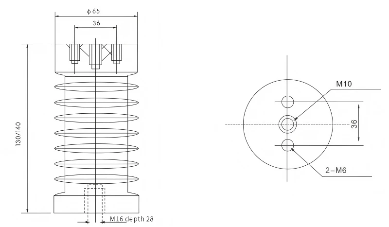
Use this 12 kV Epoxy Resin Support Insulator configuration as the starting point, then align the electrical duty, insulation requirements and mechanical interface with the switchgear assembly.
Engineering selection inputs
Selection item
Project input
Application role
12 kV Epoxy Resin Support Insulator for insulation, conductor support or a switchgear connection interface
Voltage and current scope
Initial product scope: 12 kV; include system voltage, insulation level and conductor or current duty
Insulation coordination
Specify creepage, clearance, pollution conditions, altitude, temperature and indoor or outdoor service
Conductor interface
Provide busbar, contact, cable or embedded-conductor geometry, orientation and connection details
Mechanical interface
Provide mounting face, hole centers, overall envelope, sealing arrangement and adjacent clearances
RFQ inputs
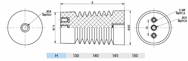
Reference 12 kV Epoxy Resin Support Insulator; attach the interface drawing, quantity, destination, standards and delivery schedule
Interface drawing
Open the full-size drawing to compare the component envelope, mounting points and switchgear interface.
12 kV 630 A Single-Side Epoxy Resin Bushing (EU Type)
Use this 12 kV 630 A Single-Side Epoxy Resin Bushing (EU Type) configuration as the starting point, then align the electrical duty, insulation requirements and mechanical interface with the switchgear assembly.
Engineering selection inputs
Selection item
Project input
Application role
12 kV 630 A Single-Side Epoxy Resin Bushing (EU Type) for insulation, conductor support or a switchgear connection interface
Voltage and current scope
Initial product scope: 12 kV, 630 A; include system voltage, insulation level and conductor or current duty
Insulation coordination
Specify creepage, clearance, pollution conditions, altitude, temperature and indoor or outdoor service
Conductor interface
Provide busbar, contact, cable or embedded-conductor geometry, orientation and connection details
Mechanical interface
Provide mounting face, hole centers, overall envelope, sealing arrangement and adjacent clearances
RFQ inputs
Reference 12 kV 630 A Single-Side Epoxy Resin Bushing (EU Type); attach the interface drawing, quantity, destination, standards and delivery schedule
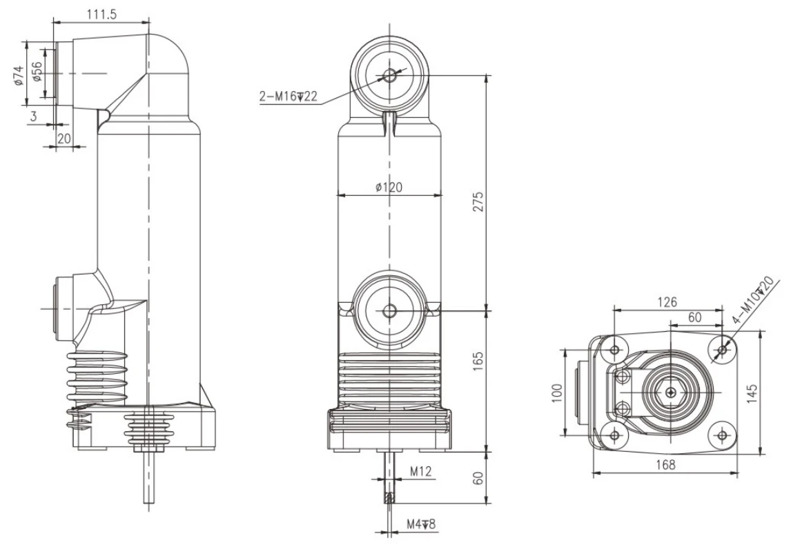
Interface drawing
Send the panel or component interface drawing with the RFQ so the mounting geometry can be coordinated.
Use this RMU Epoxy Resin Sensor configuration as the starting point, then align the electrical duty, insulation requirements and mechanical interface with the switchgear assembly.
Engineering selection inputs
Selection item
Project input
Application role
RMU Epoxy Resin Sensor for measurement, indication, automation or protection within MV switchgear
Electrical scope
Initial product scope: Define the system voltage and applicable current or mechanical duty; define the measured quantity, primary system voltage and conductor duty
Signal and secondary interface
Specify ratio or output, accuracy requirement, burden, terminal arrangement and connected device
Primary conductor and insulation
Provide the conductor route, insulation level, shielding or earthing method and service environment
Mechanical interface
Provide mounting position, hole pattern, component envelope, terminal access and panel clearances
RFQ inputs
Reference RMU Epoxy Resin Sensor; attach the SLD, panel drawing, signal requirement, quantity, destination and schedule
Interface drawing
Open the full-size drawing to compare the component envelope, mounting points and switchgear interface.
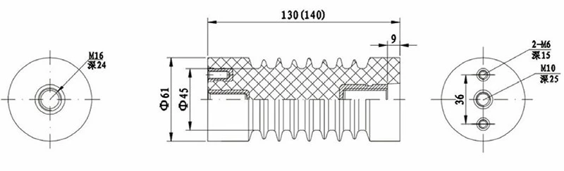
Use this Handcart Support Insulator configuration as the starting point, then align the electrical duty, insulation requirements and mechanical interface with the switchgear assembly.
Engineering selection inputs
Selection item
Project input
Application role
Handcart Support Insulator for insulation, conductor support or a switchgear connection interface
Voltage and current scope
Initial product scope: Define the system voltage and applicable current or mechanical duty; include system voltage, insulation level and conductor or current duty
Insulation coordination
Specify creepage, clearance, pollution conditions, altitude, temperature and indoor or outdoor service
Conductor interface
Provide busbar, contact, cable or embedded-conductor geometry, orientation and connection details
Mechanical interface
Provide mounting face, hole centers, overall envelope, sealing arrangement and adjacent clearances
RFQ inputs
Reference Handcart Support Insulator; attach the interface drawing, quantity, destination, standards and delivery schedule
Interface drawing
Open the full-size drawing to compare the component envelope, mounting points and switchgear interface.
Use this High-Voltage Epoxy Resin Switchgear Insulator configuration as the starting point, then align the electrical duty, insulation requirements and mechanical interface with the switchgear assembly.
Engineering selection inputs
Selection item
Project input
Application role
High-Voltage Epoxy Resin Switchgear Insulator for insulation, conductor support or a switchgear connection interface
Voltage and current scope
Initial product scope: Define the system voltage and applicable current or mechanical duty; include system voltage, insulation level and conductor or current duty
Insulation coordination
Specify creepage, clearance, pollution conditions, altitude, temperature and indoor or outdoor service
Conductor interface
Provide busbar, contact, cable or embedded-conductor geometry, orientation and connection details
Mechanical interface
Provide mounting face, hole centers, overall envelope, sealing arrangement and adjacent clearances
RFQ inputs
Reference High-Voltage Epoxy Resin Switchgear Insulator; attach the interface drawing, quantity, destination, standards and delivery schedule
Interface drawing
Open the full-size drawing to compare the component envelope, mounting points and switchgear interface.
Use this High-Voltage Epoxy Resin Switchgear Sensor configuration as the starting point, then align the electrical duty, insulation requirements and mechanical interface with the switchgear assembly.
Engineering selection inputs
Selection item
Project input
Application role
High-Voltage Epoxy Resin Switchgear Sensor for measurement, indication, automation or protection within MV switchgear
Electrical scope
Initial product scope: Define the system voltage and applicable current or mechanical duty; define the measured quantity, primary system voltage and conductor duty
Signal and secondary interface
Specify ratio or output, accuracy requirement, burden, terminal arrangement and connected device
Primary conductor and insulation
Provide the conductor route, insulation level, shielding or earthing method and service environment
Mechanical interface
Provide mounting position, hole pattern, component envelope, terminal access and panel clearances
RFQ inputs
Reference High-Voltage Epoxy Resin Switchgear Sensor; attach the SLD, panel drawing, signal requirement, quantity, destination and schedule
Interface drawing
Open the full-size drawing to compare the component envelope, mounting points and switchgear interface.
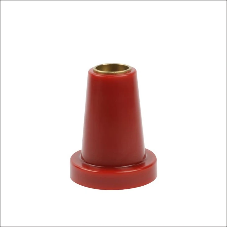
Use this 12 kV High-Voltage Support Insulator configuration as the starting point, then align the electrical duty, insulation requirements and mechanical interface with the switchgear assembly.
Engineering selection inputs
Selection item
Project input
Application role
12 kV High-Voltage Support Insulator for insulation, conductor support or a switchgear connection interface
Voltage and current scope
Initial product scope: 12 kV; include system voltage, insulation level and conductor or current duty
Insulation coordination
Specify creepage, clearance, pollution conditions, altitude, temperature and indoor or outdoor service
Conductor interface
Provide busbar, contact, cable or embedded-conductor geometry, orientation and connection details
Mechanical interface
Provide mounting face, hole centers, overall envelope, sealing arrangement and adjacent clearances
RFQ inputs
Reference 12 kV High-Voltage Support Insulator; attach the interface drawing, quantity, destination, standards and delivery schedule
Interface drawing
Send the panel or component interface drawing with the RFQ so the mounting geometry can be coordinated.
Use this 12 kV Epoxy Resin Insulated Tube configuration as the starting point, then align the electrical duty, insulation requirements and mechanical interface with the switchgear assembly.
Engineering selection inputs
Selection item
Project input
Application role
12 kV Epoxy Resin Insulated Tube for insulation, conductor support or a switchgear connection interface
Voltage and current scope
Initial product scope: 12 kV; include system voltage, insulation level and conductor or current duty
Insulation coordination
Specify creepage, clearance, pollution conditions, altitude, temperature and indoor or outdoor service
Conductor interface
Provide busbar, contact, cable or embedded-conductor geometry, orientation and connection details
Mechanical interface
Provide mounting face, hole centers, overall envelope, sealing arrangement and adjacent clearances
RFQ inputs
Reference 12 kV Epoxy Resin Insulated Tube; attach the interface drawing, quantity, destination, standards and delivery schedule
Interface drawing
Open the full-size drawing to compare the component envelope, mounting points and switchgear interface.
Use this High-Voltage Switchgear Insulator configuration as the starting point, then align the electrical duty, insulation requirements and mechanical interface with the switchgear assembly.
Engineering selection inputs
Selection item
Project input
Application role
High-Voltage Switchgear Insulator for insulation, conductor support or a switchgear connection interface
Voltage and current scope
Initial product scope: Define the system voltage and applicable current or mechanical duty; include system voltage, insulation level and conductor or current duty
Insulation coordination
Specify creepage, clearance, pollution conditions, altitude, temperature and indoor or outdoor service
Conductor interface
Provide busbar, contact, cable or embedded-conductor geometry, orientation and connection details
Mechanical interface
Provide mounting face, hole centers, overall envelope, sealing arrangement and adjacent clearances
RFQ inputs
Reference High-Voltage Switchgear Insulator; attach the interface drawing, quantity, destination, standards and delivery schedule
Interface drawing
Open the full-size drawing to compare the component envelope, mounting points and switchgear interface.
Use this Indoor High-Voltage Epoxy Resin Insulator configuration as the starting point, then align the electrical duty, insulation requirements and mechanical interface with the switchgear assembly.
Engineering selection inputs
Selection item
Project input
Application role
Indoor High-Voltage Epoxy Resin Insulator for insulation, conductor support or a switchgear connection interface
Voltage and current scope
Initial product scope: Define the system voltage and applicable current or mechanical duty; include system voltage, insulation level and conductor or current duty
Insulation coordination
Specify creepage, clearance, pollution conditions, altitude, temperature and indoor or outdoor service
Conductor interface
Provide busbar, contact, cable or embedded-conductor geometry, orientation and connection details
Mechanical interface
Provide mounting face, hole centers, overall envelope, sealing arrangement and adjacent clearances
RFQ inputs
Reference Indoor High-Voltage Epoxy Resin Insulator; attach the interface drawing, quantity, destination, standards and delivery schedule
Interface drawing
Open the full-size drawing to compare the component envelope, mounting points and switchgear interface.
Use this Switchgear Support and Busbar Insulators configuration as the starting point, then align the electrical duty, insulation requirements and mechanical interface with the switchgear assembly.
Engineering selection inputs
Selection item
Project input
Application role
Switchgear Support and Busbar Insulators for insulation, conductor support or a switchgear connection interface
Voltage and current scope
Initial product scope: Define the system voltage and applicable current or mechanical duty; include system voltage, insulation level and conductor or current duty
Insulation coordination
Specify creepage, clearance, pollution conditions, altitude, temperature and indoor or outdoor service
Conductor interface
Provide busbar, contact, cable or embedded-conductor geometry, orientation and connection details
Mechanical interface
Provide mounting face, hole centers, overall envelope, sealing arrangement and adjacent clearances
RFQ inputs
Reference Switchgear Support and Busbar Insulators; attach the interface drawing, quantity, destination, standards and delivery schedule
Interface drawing
Open the full-size drawing to compare the component envelope, mounting points and switchgear interface.
Use this KYN61 Two-Way Shielded Insulating Contact Box configuration as the starting point, then align the electrical duty, insulation requirements and mechanical interface with the switchgear assembly.
Engineering selection inputs
Selection item
Project input
Application role
KYN61 Two-Way Shielded Insulating Contact Box for the switchgear primary contact and insulation interface
Voltage and current duty
Initial product scope: Define the system voltage and applicable current or mechanical duty; include system voltage, continuous current, conductor size and temperature-rise conditions
Primary contact interface
Specify fixed or moving contact arrangement, conductor orientation, contact diameter and connection details
Insulation and phase layout
Provide phase spacing, clearance envelope, earthing or shielding arrangement and indoor service conditions
Mechanical interface
Provide panel mounting face, hole centers, overall envelope, busbar route and adjacent-component clearances
RFQ inputs
Reference KYN61 Two-Way Shielded Insulating Contact Box; attach the panel GA or interface drawing, quantity, destination, standards and delivery schedule
Interface drawing
Send the panel or component interface drawing with the RFQ so the mounting geometry can be coordinated.
Use this KYN61 Shielded Tee Insulating Contact Box configuration as the starting point, then align the electrical duty, insulation requirements and mechanical interface with the switchgear assembly.
Engineering selection inputs
Selection item
Project input
Application role
KYN61 Shielded Tee Insulating Contact Box for the switchgear primary contact and insulation interface
Voltage and current duty
Initial product scope: Define the system voltage and applicable current or mechanical duty; include system voltage, continuous current, conductor size and temperature-rise conditions
Primary contact interface
Specify fixed or moving contact arrangement, conductor orientation, contact diameter and connection details
Insulation and phase layout
Provide phase spacing, clearance envelope, earthing or shielding arrangement and indoor service conditions
Mechanical interface
Provide panel mounting face, hole centers, overall envelope, busbar route and adjacent-component clearances
RFQ inputs
Reference KYN61 Shielded Tee Insulating Contact Box; attach the panel GA or interface drawing, quantity, destination, standards and delivery schedule
Interface drawing
Open the full-size drawing to compare the component envelope, mounting points and switchgear interface.
Use this 12/24/36 kV Epoxy Resin Through-Wall Bushing configuration as the starting point, then align the electrical duty, insulation requirements and mechanical interface with the switchgear assembly.
Engineering selection inputs
Selection item
Project input
Application role
12/24/36 kV Epoxy Resin Through-Wall Bushing for insulation, conductor support or a switchgear connection interface
Voltage and current scope
Initial product scope: 12/24/36 kV; include system voltage, insulation level and conductor or current duty
Insulation coordination
Specify creepage, clearance, pollution conditions, altitude, temperature and indoor or outdoor service
Conductor interface
Provide busbar, contact, cable or embedded-conductor geometry, orientation and connection details
Mechanical interface
Provide mounting face, hole centers, overall envelope, sealing arrangement and adjacent clearances
RFQ inputs
Reference 12/24/36 kV Epoxy Resin Through-Wall Bushing; attach the interface drawing, quantity, destination, standards and delivery schedule
Interface drawing
Open the full-size drawing to compare the component envelope, mounting points and switchgear interface.
Use this 12/24/36 kV High-Voltage Epoxy Resin Insulator configuration as the starting point, then align the electrical duty, insulation requirements and mechanical interface with the switchgear assembly.
Engineering selection inputs
Selection item
Project input
Application role
12/24/36 kV High-Voltage Epoxy Resin Insulator for insulation, conductor support or a switchgear connection interface
Voltage and current scope
Initial product scope: 12/24/36 kV; include system voltage, insulation level and conductor or current duty
Insulation coordination
Specify creepage, clearance, pollution conditions, altitude, temperature and indoor or outdoor service
Conductor interface
Provide busbar, contact, cable or embedded-conductor geometry, orientation and connection details
Mechanical interface
Provide mounting face, hole centers, overall envelope, sealing arrangement and adjacent clearances
RFQ inputs
Reference 12/24/36 kV High-Voltage Epoxy Resin Insulator; attach the interface drawing, quantity, destination, standards and delivery schedule
Interface drawing
Send the panel or component interface drawing with the RFQ so the mounting geometry can be coordinated.
Define the Electrical Duty and Switchgear Interface
Use the product cards to identify the component family, then provide the electrical, insulation and mechanical inputs needed to prepare a model-specific quotation.
01
Electrical duty
System nominal voltage, highest voltage for equipment, rated current or sensing function, insulation level, frequency and applicable standard.
02
Insulation environment
Indoor or outdoor service, pollution conditions, creepage and clearance targets, altitude, temperature, humidity, shielding and earthing.
03
Primary interface
Busbar, contact, cable or embedded-conductor size; phase layout; current path; terminal geometry; sealing route and connection orientation.
04
Mechanical interface
Panel general arrangement, component envelope, mounting face, hole centers, tolerances, adjacent clearances and installation direction.
05
Sensor requirements
Measured quantity, ratio or output, accuracy, burden, protection or indication duty, secondary terminals and connected device.
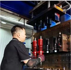
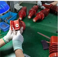
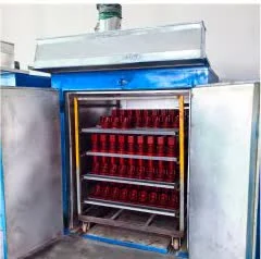
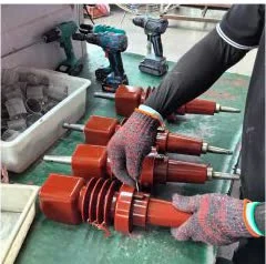
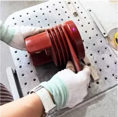
A representative production sequence from molding and edge preparation through drying, finishing, marking and dispatch checks.
01
Injection Molding
Form the epoxy resin component and embedded conductive or mounting interfaces.
02
Mechanical Deburring
Remove molding flash and prepare edges, holes and interfaces for the next operation.
03
Rotary Drying
Stabilize the molded component through the controlled drying stage.
04
Polishing
Finish accessible surfaces and prepare the component for marking and inspection.
05
Laser Nameplate
Apply component identification and project-specific marking requirements.
06
Finished Product
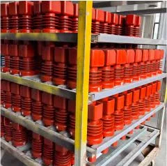
Complete final visual, dimensional, documentation and packing checks for dispatch.
Related MV switchgear components
Related MV Switchgear Components
Compare switching, operating and circuit-interruption equipment commonly reviewed with epoxy resin insulation components in medium-voltage switchgear assemblies.
Technical FAQ
Epoxy Resin Switchgear Component FAQ
Selection guidance for insulators, bushings, contact boxes, sensors and mounting hardware used in medium-voltage switchgear.
Which epoxy resin components are covered on this page?
The range includes switchgear insulator plugs, support insulators, bushings, insulated tubes, contact boxes, sensor components and mounting hardware for medium-voltage panel assemblies.
What information is needed to select an epoxy resin switchgear component?
Provide the component function, switchgear type, system voltage, rated current or sensing duty, conductor arrangement, mounting position, interface drawing, service conditions, quantity and destination.
How should insulators, contact boxes and sensors be compared?
For insulators and bushings, compare insulation duty, creepage, conductor path and mounting geometry. For contact boxes, add current duty, contact interface, phase spacing and temperature-rise conditions. For sensors, define the measured quantity, ratio or output, accuracy requirement, primary conductor route and secondary interface.
What should an epoxy resin component RFQ include?
Send the product name or image, panel general arrangement, electrical duty, mounting dimensions, drawing revision, environmental conditions, applicable standards, inspection-document requirements, quantity, delivery destination and schedule.
Request an Epoxy Resin Component RFQ
Send the selected component name or image together with the electrical duty, panel interface and delivery scope. SUVELL will coordinate the configuration and quotation around your switchgear assembly.