Send the request type, manufacturer, equipment model/year, part reference, ratings, quantity, destination, required date, and any drawing or photo notes. The SUVELL team will review the request.
Email: admin@suvell.com
Phone: +86 189 6871 1705
Factory: No.208 Wei 12 Rd, Yueqing Economic Development Zone, Wenzhou, Zhejiang, China
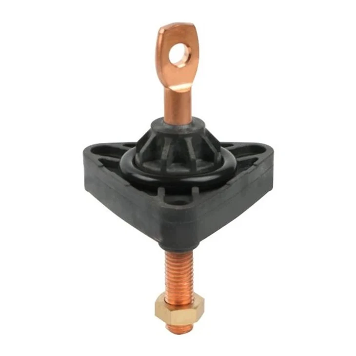
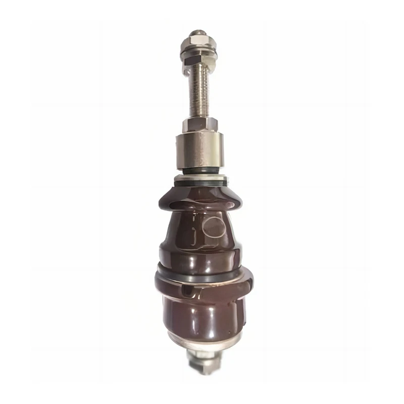
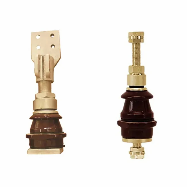
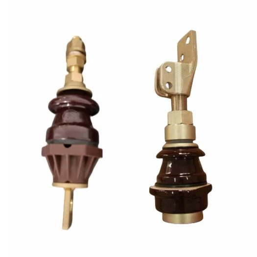
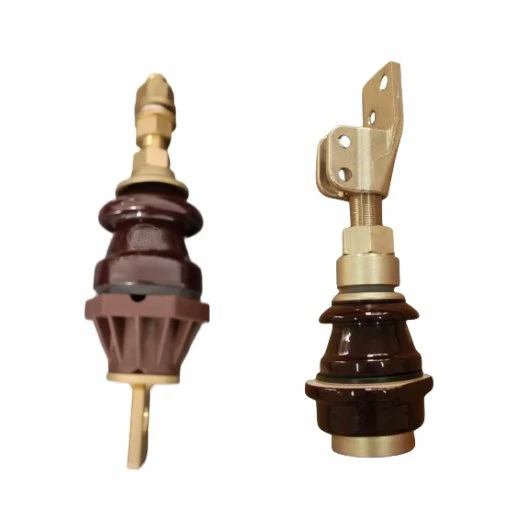
Compare epoxy molded, integral tri-clamp and porcelain low voltage transformer bushings for liquid-filled distribution transformer secondary connections. Select by rated current, terminal arrangement, tank-wall mounting and sealing interface.
Choose the insulation and mounting family, then compare the available rated-current configuration, terminal or conductor arrangement, tank-wall interface, sealing and drawing details.
Epoxy secondary
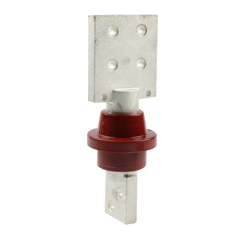
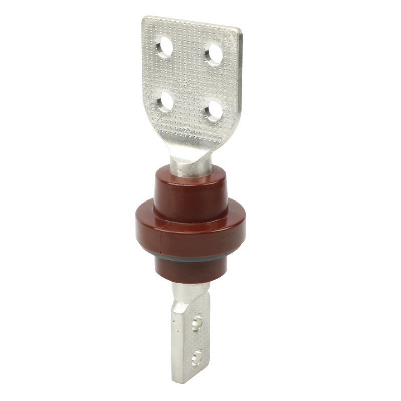
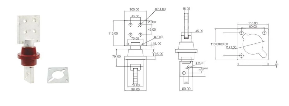
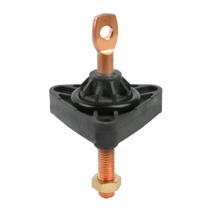
1.2 kV 3000 A Epoxy LV Bushing
1.2 kV, 3000 A epoxy secondary bushing for liquid-filled transformer tank-wall interfaces, with copper or aluminum conductor selection.
View ratings and interface →
Epoxy secondary
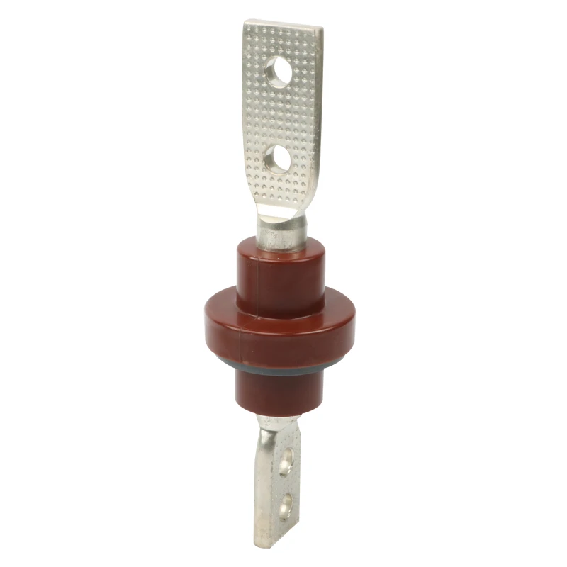
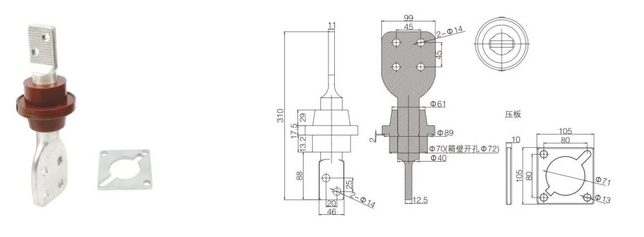
1.2 kV 2000 A Epoxy LV Bushing
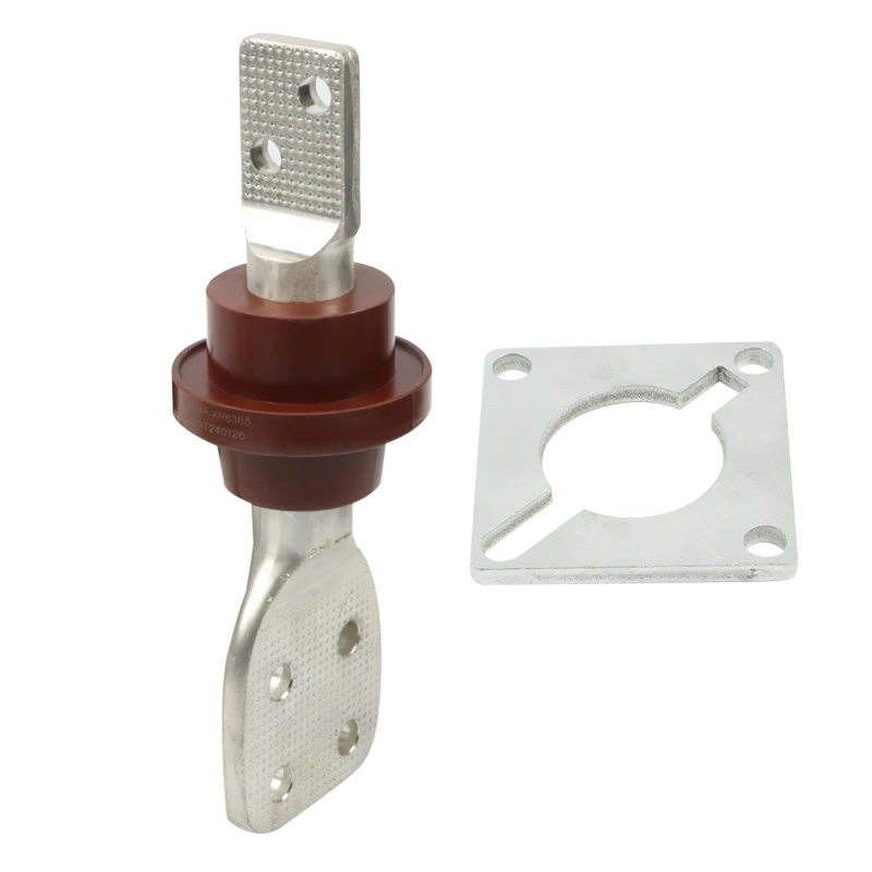
1.2 kV, 2000 A epoxy secondary bushing for liquid-filled transformer tank-wall interfaces, with conductor and terminal details coordinated to the drawing.
View ratings and interface →
Epoxy secondary
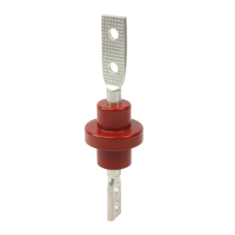
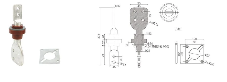
1.2 kV 1600 A Epoxy LV Bushing
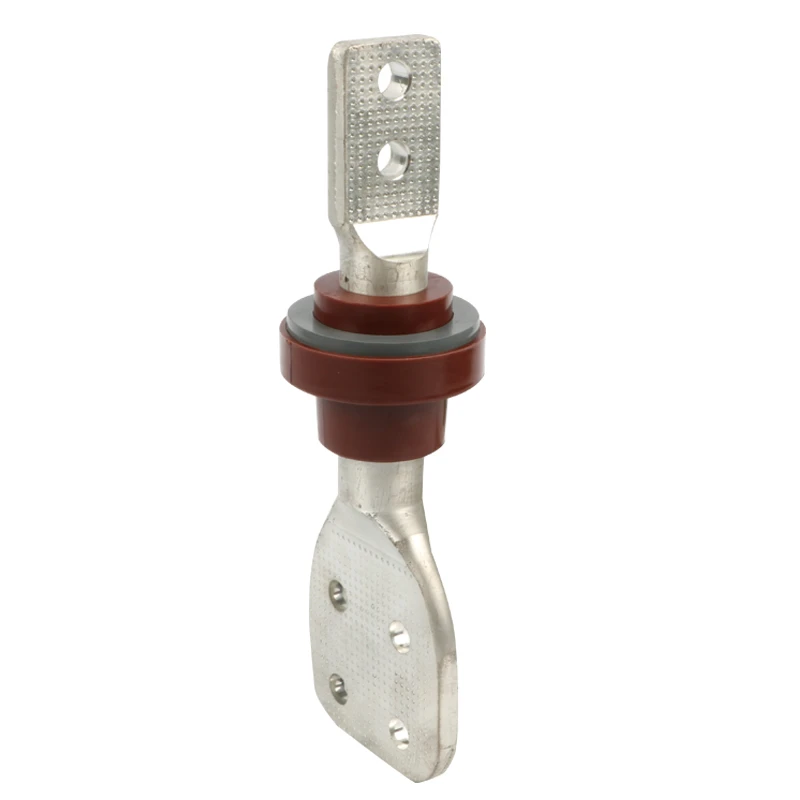
1.2 kV, 1600 A epoxy secondary bushing for transformer tank-wall mounting, terminal arrangement and sealing coordination.
View ratings and interface →
Epoxy secondary
1.2 kV 1000 A Epoxy LV Bushing
1.2 kV, 1000 A epoxy secondary bushing for liquid-filled transformer applications, with copper or aluminum conductor alternatives.
View ratings and interface →
Epoxy secondary
630 A Epoxy LV Bushing
630 A epoxy low voltage transformer bushing for secondary-side terminal, tank-wall mounting and sealing review.
View ratings and interface →
Epoxy secondary
400 A Low Voltage Epoxy Resin Bushing
400 A epoxy resin low voltage bushing for transformer secondary connections and drawing-based interface coordination.
View ratings and interface →
Tri-clamp secondary
5/8 in Integral Clamp Bushing
1.2 kV integral clamp transformer bushing with a 5/8-inch interface for tank-hole, gasket, conductor and terminal selection.
View ratings and interface →
Tri-clamp secondary
1 in Integral Clamp Bushing
1.2 kV, 1200 A integral clamp transformer bushing with flange mounting, gasket and stud-terminal coordination.
View ratings and interface →
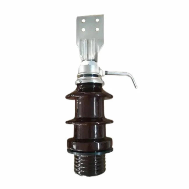
Porcelain bushing
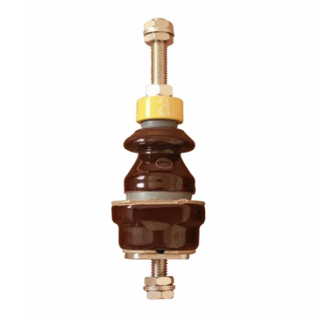
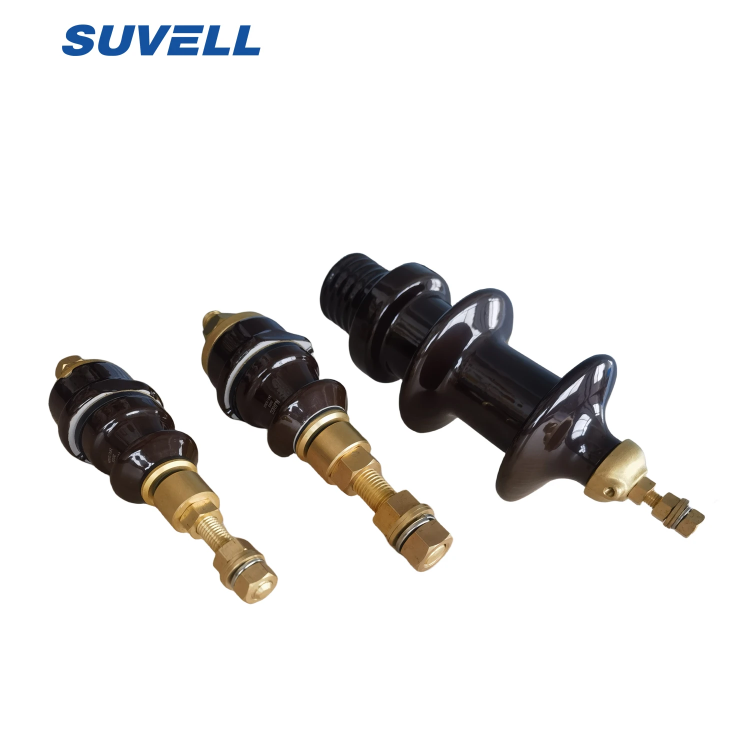
1 kV 250 A Porcelain Bushing
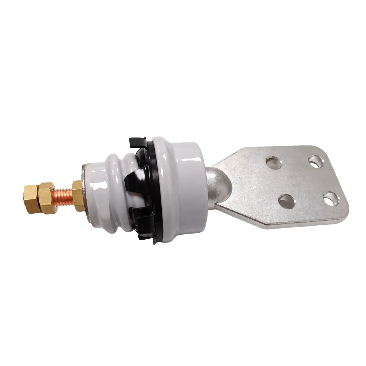
1 kV, 250 A porcelain transformer bushing for secondary terminal, mounting face, conductor and sealing selection.
View ratings and interface →
Porcelain bushing
1 kV 400 A Porcelain Bushing
1 kV, 400 A porcelain transformer bushing for tank-wall mounting, terminal arrangement and clearance coordination.
View ratings and interface →
Porcelain bushing
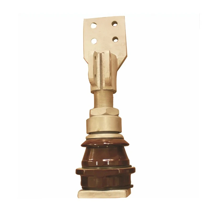
1 kV 800 A Porcelain Bushing
1 kV, 800 A porcelain transformer bushing for secondary-side electrical duty and drawing-based mechanical interface review.
View ratings and interface →
Porcelain bushing
200 A to 3000 A Porcelain Bushing
Porcelain low voltage transformer bushing range for 200 A to 3000 A applications, selected by rating, terminal, mounting and sealing interface.
View ratings and interface →
Epoxy secondary
1.2 kV 3000 A Epoxy LV Bushing
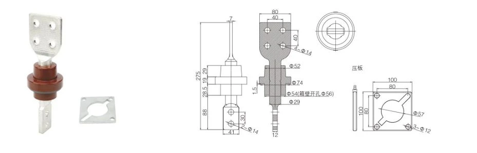
Review the configuration values and product image or drawing below. Coordinate the terminal arrangement, conductor, tank-wall mounting, sealing, clearances and required documents before quotation.
Engineering drawing
On small screens, scroll the table horizontally.
Selection parameter
Configuration value
Rated voltage
1.2 kV
Rated current
3000 A
Application
Secondary bushing in liquid-filled transformers
Conductor alternatives
Copper or aluminum
Copper conductor construction
C110 electrolytic copper with silver-brazed connections
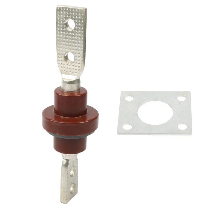
Review the configuration values and product image or drawing below. Coordinate the terminal arrangement, conductor, tank-wall mounting, sealing, clearances and required documents before quotation.
Engineering drawing
On small screens, scroll the table horizontally.
Selection parameter
Configuration value
Rated voltage
1.2 kV
Rated current
2000 A
Application
Secondary bushing in liquid-filled transformers
Conductor alternatives
Copper or aluminum
Copper conductor construction
C110 electrolytic copper with silver-brazed connections
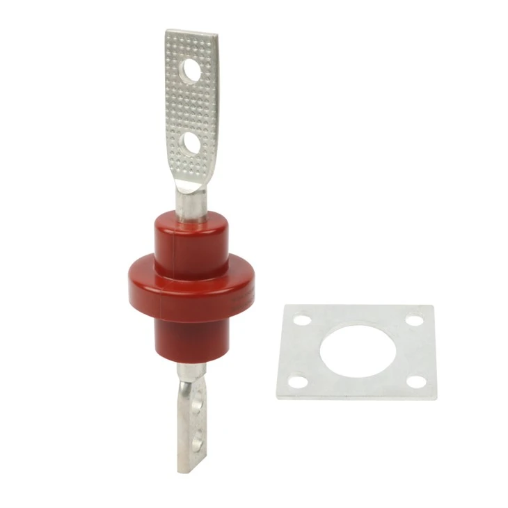
Review the configuration values and product image or drawing below. Coordinate the terminal arrangement, conductor, tank-wall mounting, sealing, clearances and required documents before quotation.
Engineering drawing
On small screens, scroll the table horizontally.
Selection parameter
Configuration value
Rated voltage
1.2 kV
Rated current
1600 A
Application
Secondary bushing in liquid-filled transformers
Conductor alternatives
Copper or aluminum
Copper conductor construction
C110 electrolytic copper with silver-brazed connections
Review the configuration values and product image or drawing below. Coordinate the terminal arrangement, conductor, tank-wall mounting, sealing, clearances and required documents before quotation.
Engineering drawing
On small screens, scroll the table horizontally.
Selection parameter
Configuration value
Rated voltage
1.2 kV
Rated current
1000 A
Application
Secondary bushing in liquid-filled transformers
Conductor alternatives
Copper or aluminum
Copper conductor construction
C110 electrolytic copper with silver-brazed connections
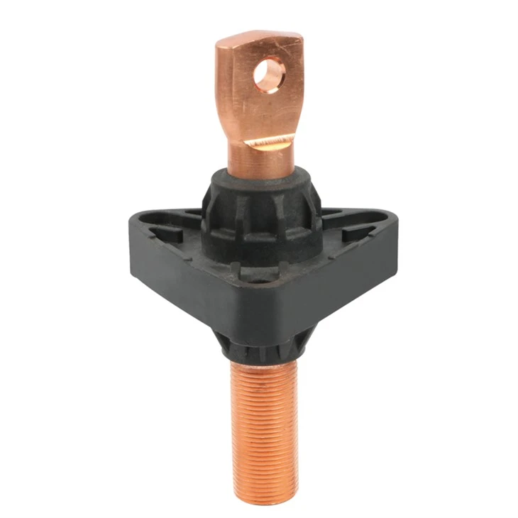
Review the configuration values and product image or drawing below. Coordinate the terminal arrangement, conductor, tank-wall mounting, sealing, clearances and required documents before quotation.
Product interface view
On small screens, scroll the table horizontally.
Selection parameter
Configuration value
Rated voltage
1.2 kV
Rated current
630 A
Application
Secondary bushing in liquid-filled transformers
Conductor alternatives
Copper or aluminum
Copper conductor construction
C110 electrolytic copper with silver-brazed connections
Review the configuration values and product image or drawing below. Coordinate the terminal arrangement, conductor, tank-wall mounting, sealing, clearances and required documents before quotation.
Product interface view
On small screens, scroll the table horizontally.
Selection parameter
Configuration value
Rated voltage
1.2 kV
Rated current
400 A
Application
Secondary bushing in liquid-filled transformers
Conductor alternatives
Copper or aluminum
Copper conductor construction
C110 electrolytic copper with silver-brazed connections
Review the configuration values and product image or drawing below. Coordinate the terminal arrangement, conductor, tank-wall mounting, sealing, clearances and required documents before quotation.
Review the configuration values and product image or drawing below. Coordinate the terminal arrangement, conductor, tank-wall mounting, sealing, clearances and required documents before quotation.
Review the configuration values and product image or drawing below. Coordinate the terminal arrangement, conductor, tank-wall mounting, sealing, clearances and required documents before quotation.
Product interface view
On small screens, scroll the table horizontally.
Selection parameter
Configuration value
Rated designation
1 kV / 250 A
Porcelain family reference — 1 kV (max / 60 s PF dry / damp / impulse dry)
— / 8 kV / — / —
Porcelain family reference — 6 kV (max / 60 s PF dry / damp / impulse dry)
7.2 kV / 26 kV / 23 kV / 60 kV
Porcelain family reference — 10 kV (max / 60 s PF dry / damp / impulse dry)
12 kV / 42 kV / 30 kV / 75 kV
Porcelain family reference — 20 kV (max / 60 s PF dry / damp / impulse dry)
24 kV / 58 kV / 50 kV / 125 kV
Porcelain family reference — 35 kV (max / 60 s PF dry / damp / impulse dry)
40.5 kV / 98 kV / 80 kV / 200 kV
Porcelain family reference — 66 kV (max / 60 s PF dry / damp / impulse dry)
Review the configuration values and product image or drawing below. Coordinate the terminal arrangement, conductor, tank-wall mounting, sealing, clearances and required documents before quotation.
Product interface view
On small screens, scroll the table horizontally.
Selection parameter
Configuration value
Rated designation
1 kV / 400 A
Porcelain family reference — 1 kV (max / 60 s PF dry / damp / impulse dry)
— / 8 kV / — / —
Porcelain family reference — 6 kV (max / 60 s PF dry / damp / impulse dry)
7.2 kV / 26 kV / 23 kV / 60 kV
Porcelain family reference — 10 kV (max / 60 s PF dry / damp / impulse dry)
12 kV / 42 kV / 30 kV / 75 kV
Porcelain family reference — 20 kV (max / 60 s PF dry / damp / impulse dry)
24 kV / 58 kV / 50 kV / 125 kV
Porcelain family reference — 35 kV (max / 60 s PF dry / damp / impulse dry)
40.5 kV / 98 kV / 80 kV / 200 kV
Porcelain family reference — 66 kV (max / 60 s PF dry / damp / impulse dry)
Review the configuration values and product image or drawing below. Coordinate the terminal arrangement, conductor, tank-wall mounting, sealing, clearances and required documents before quotation.
Product interface view
On small screens, scroll the table horizontally.
Selection parameter
Configuration value
Rated designation
1 kV / 800 A
Porcelain family reference — 1 kV (max / 60 s PF dry / damp / impulse dry)
— / 8 kV / — / —
Porcelain family reference — 6 kV (max / 60 s PF dry / damp / impulse dry)
7.2 kV / 26 kV / 23 kV / 60 kV
Porcelain family reference — 10 kV (max / 60 s PF dry / damp / impulse dry)
12 kV / 42 kV / 30 kV / 75 kV
Porcelain family reference — 20 kV (max / 60 s PF dry / damp / impulse dry)
24 kV / 58 kV / 50 kV / 125 kV
Porcelain family reference — 35 kV (max / 60 s PF dry / damp / impulse dry)
40.5 kV / 98 kV / 80 kV / 200 kV
Porcelain family reference — 66 kV (max / 60 s PF dry / damp / impulse dry)
Review the configuration values and product image or drawing below. Coordinate the terminal arrangement, conductor, tank-wall mounting, sealing, clearances and required documents before quotation.
Product interface view
On small screens, scroll the table horizontally.
Selection parameter
Configuration value
Rated designation
200 A to 3000 A
Porcelain family reference — 1 kV (max / 60 s PF dry / damp / impulse dry)
— / 8 kV / — / —
Porcelain family reference — 6 kV (max / 60 s PF dry / damp / impulse dry)
7.2 kV / 26 kV / 23 kV / 60 kV
Porcelain family reference — 10 kV (max / 60 s PF dry / damp / impulse dry)
12 kV / 42 kV / 30 kV / 75 kV
Porcelain family reference — 20 kV (max / 60 s PF dry / damp / impulse dry)
24 kV / 58 kV / 50 kV / 125 kV
Porcelain family reference — 35 kV (max / 60 s PF dry / damp / impulse dry)
40.5 kV / 98 kV / 80 kV / 200 kV
Porcelain family reference — 66 kV (max / 60 s PF dry / damp / impulse dry)
After selecting a low voltage bushing configuration, align conductor material, terminal type, tank-wall opening, mounting face, sealing, electrical duty, inspection documents, packing and destination in one quotation scope.
External terminalTransformer tank wallInternal conductorIllustrative secondary-interface topology. Use the selected configuration drawing to coordinate the final terminal, tank wall, conductor and clearance arrangement.
Confirm the Required Transformer Bushing Inputs
Electrical duty and terminal arrangement
State rated voltage and current, conductor material, terminal form, plating, connection orientation and transformer secondary-circuit requirements.
Tank-wall mounting and sealing
Provide the tank-wall opening, flange or clamp, mounting face, gasket, clearances, transformer layout and any dimensional constraints.
Documents and commercial scope
Include drawings, interface photos, nameplate details, quantity, destination, inspection requirements, marking, packing and requested delivery timing.
Coordinate Production, Inspection and Delivery
Keep the selected configuration, electrical and mechanical interfaces, documentation, inspection and delivery requirements together for engineering and commercial review.
OEM / ODM production coordination
Coordinate terminal options, interface geometry, conductor, marking and transformer integration requirements with the selected configuration.
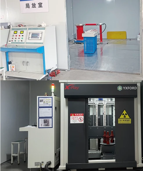
Inspection and test documentation
Define required inspections, test records, traceability, nameplate details and document language for the order.
Packing and delivery planning
State quantity, destination, packing method, logistics constraints, requested schedule and replacement or project-stock use.
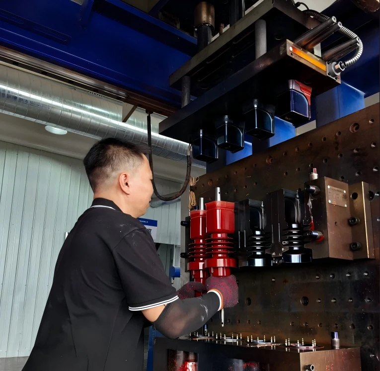
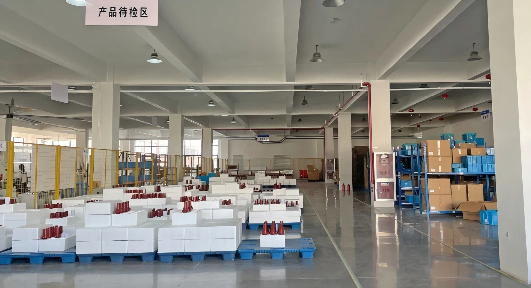
Manufacturing process
Manufacturing &Quality Control
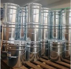
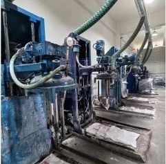
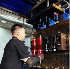
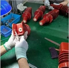
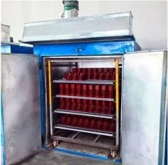
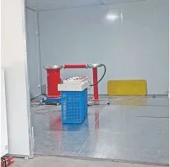
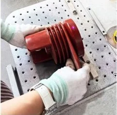
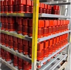
The nine-step sequence shows material preparation, mixing, molding, finishing, testing, marking and finished-product staging for low voltage bushing production and order coordination.
Raw materialsProcess 01
Automatic mixingProcess 02
Injection moldingProcess 03
Mechanical deburringProcess 04
Rotary dryerProcess 05
PolishingProcess 06
TestingProcess 07
Laser nameplateProcess 08
Finished productProcess 09
Related transformer components
Related Components
Coordinate the low voltage bushing with the primary-side bushing, transformer protection and monitoring components required for the same transformer scope.
Use these answers to compare bushing construction, ratings, terminal arrangements, tank-wall interfaces and the inputs needed for quotation.
How do I choose a low voltage transformer bushing family?
Start with the transformer secondary connection, insulation construction, rated current, tank-wall mounting method and terminal form. Then compare epoxy molded, integral tri-clamp and porcelain configurations against the required electrical and mechanical interface.
What information is needed for a replacement bushing RFQ?
Provide the existing bushing nameplate or designation, front and side photos, transformer position, rated voltage and current, mounting opening, flange or clamp arrangement, conductor and terminal details, gasket condition, dimensions and available drawing.
What is the difference between epoxy, tri-clamp and porcelain bushings?
Epoxy molded bushings support compact secondary interfaces across several current ratings. Integral tri-clamp bushings use an external clamp and gasket arrangement. Porcelain bushings are selected around the porcelain body, terminal arrangement, mounting face, sealing and required electrical duty.
Which electrical and mechanical details must be coordinated?
Coordinate rated voltage and current, withstand or insulation requirements, conductor material, terminal type and orientation, tank-wall opening, flange or clamp, gasket, clearances, creepage where applicable and the final outline drawing.
Can terminal and mounting arrangements be customized?
Terminal, conductor, plating, mounting and sealing alternatives can be reviewed against the selected configuration. Include the transformer interface, continuous-current duty, dimensional constraints, quantity and required documents with the inquiry.
Request engineering support
Request a Bushing RFQ
Send the selected bushing configuration with the transformer rating, secondary interface, mounting, sealing, drawing, quantity, document and delivery requirements.
Include these RFQ inputs
Rated voltage, current and insulation requirementsEpoxy, integral tri-clamp or porcelain configurationTank-wall opening, flange or clamp and gasketTerminal, conductor, plating and orientationDrawing, photos, nameplate and dimensional constraintsQuantity, documents, packing, destination and schedule