Send the request type, manufacturer, equipment model/year, part reference, ratings, quantity, destination, required date, and any drawing or photo notes. The SUVELL team will review the request.
Email: admin@suvell.com
Phone: +86 189 6871 1705
Factory: No.208 Wei 12 Rd, Yueqing Economic Development Zone, Wenzhou, Zhejiang, China
Choose a voltage family, then open its technical table and engineering drawing. Add the required cabinet interface, operating mechanism, and switching duty to the RFQ.
Indoor switch family
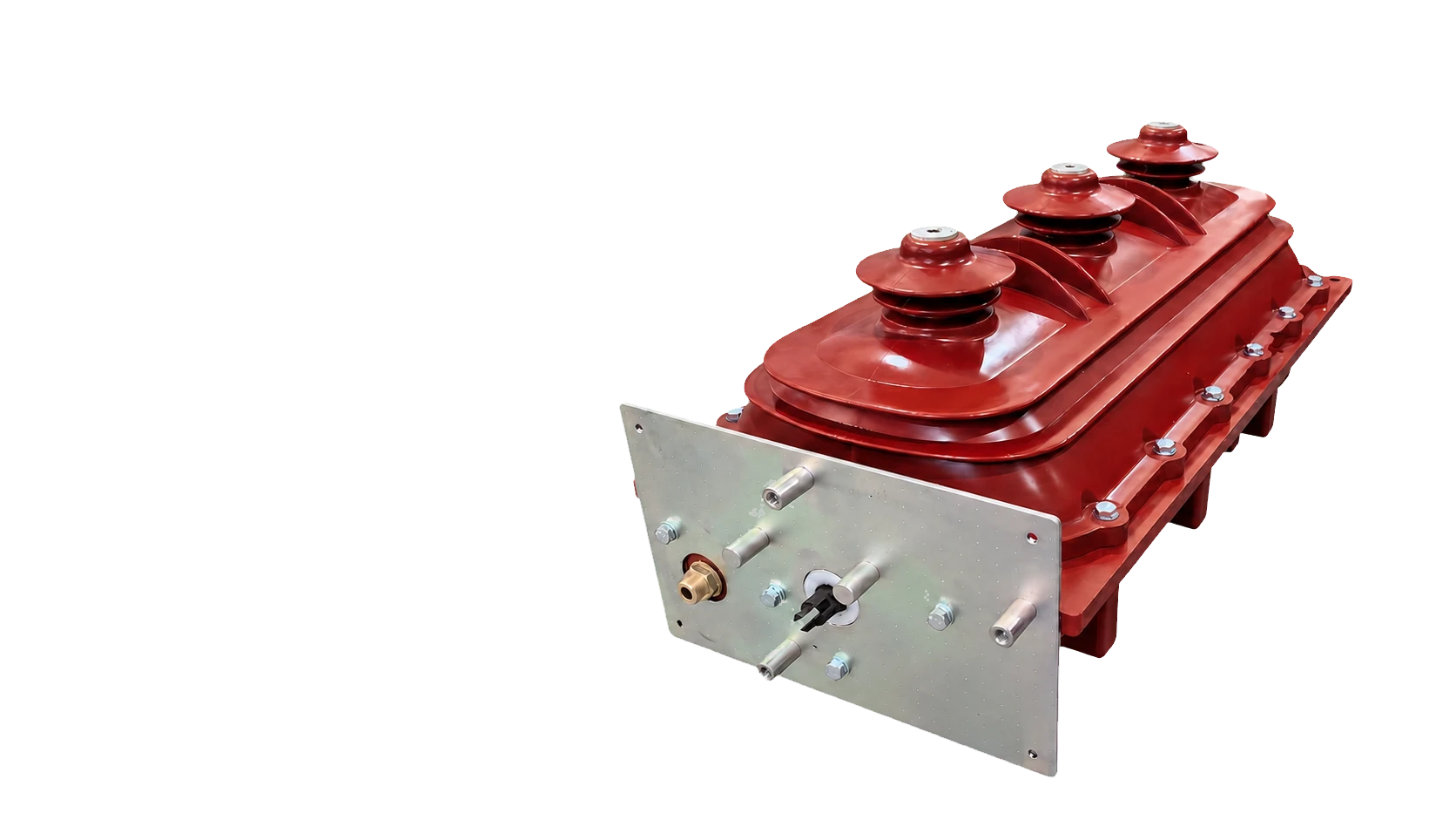
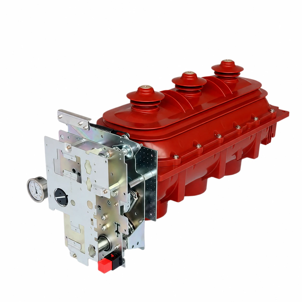
12 kV, 630 A SF6 load break switch
Compare the 12 kV, 630 A rating, insulation levels, partial-discharge value, operating options, and drawing reference for an RMU or GIS assembly.
Review ratings and drawing ↗
Indoor switch family
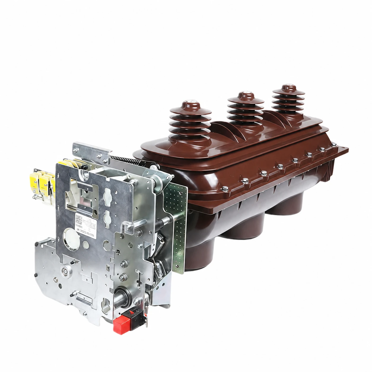
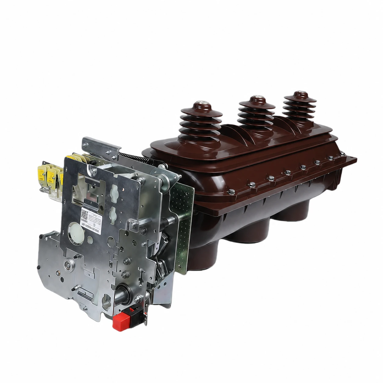
24 kV, 630 A SF6 load break switch
Review the 24 kV, 630 A rating, insulation levels, mechanism and interface options, test values, and engineering drawing for the cabinet design.
Review ratings and drawing ↗
Indoor switch family
35 kV SF6 load break switch layout
Use the 35 kV configuration and drawing to review the dimensional envelope and manufacturing requirements before requesting the final electrical schedule.
Review ratings and drawing ↗
Engineering specification
Prepare an RMU or GIS load break switch specification
Match the switch to the required electrical duty and installation interface before quotation. Send the cabinet layout, connection details, mechanism requirements, and quantity so the correct configuration can be prepared.
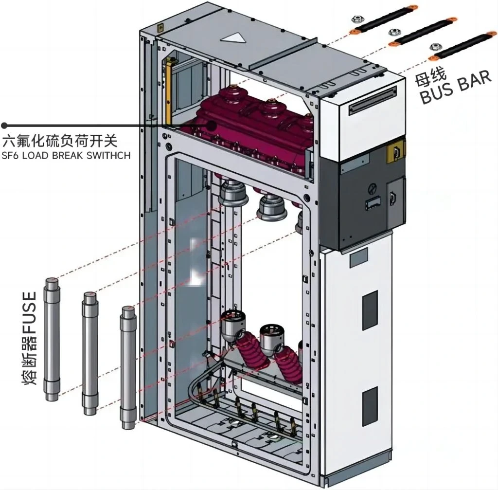
RMU and GIS interface guide: define the actual busbar, fuse, cable, bushing, interlocking, earthing, mounting, and clearance arrangement for the selected cabinet.
Define the installation and operating interface
Cabinet mounting, clearances, and phase spacing
Provide the cabinet general arrangement, mounting pattern, operating position, phase spacing, and accessible working envelope.
Busbar, cable, and bushing connection interface
State the terminal interface, conductor orientation, connection arrangement, and available cable or bushing clearance.
Operating mechanism, interlocking, and earthing
State the required manual or motor operation, shaft direction, interlock logic, earthing arrangement, and control supply.
Send an engineering RFQ package
Keep the voltage family, rated current, duty, project interface, quantity, drawing revision, and required documents together so the review starts from the right configuration.
OEM / ODM configuration
For non-standard work, identify the cabinet envelope, interface constraints, operating arrangement, and nameplate or marking requirements.
Inspection and traceability requirements
State the routine-test, inspection, traceability, and quality-document requirements for the selected configuration.
Delivery and packing scope
State the destination, quantity, shipment basis, packing expectations, and requested delivery window.
Continue your RMU and GIS component selection
Move from load-break-switch selection to the adjacent switching, monitoring, and operating components that share the same medium-voltage cabinet scope.
SF6 load break switch selection FAQ
Use the configuration data, intended switching duty, applicable standard, and cabinet interface together when preparing the enquiry.
Which SF6 load break switch voltage families are shown on this page?
The page presents 12 kV and 24 kV, 630 A configurations plus a 35 kV layout. Open each card to keep the technical table and engineering drawing together during RMU or GIS selection.
Which duty and interface inputs are needed to select a load break switch?
Start with system voltage, normal current, insulation coordination, switching duty, earthing and interlocking arrangement, operating mechanism, control supply, cabinet mounting, and the connection interface.
What files should accompany an RMU or GIS load break switch RFQ?
Send the cabinet general arrangement, single-line diagram where available, connection or bushing detail, mounting pattern, operating arrangement, quantity, applicable standard, drawing revision, and available nameplate or site photographs.
Why should the applicable standard be included in the enquiry?
The applicable standard defines the switching duty and test basis for the requested configuration. State the project standard, such as IEC 62271-103 where relevant, together with any customer-specific acceptance requirements.
Request SF6 switch quotation.
Send the voltage, normal current, switching duty, applicable standard, cabinet interface, operating arrangement, quantity, destination, and available drawings for a configuration and quotation review.
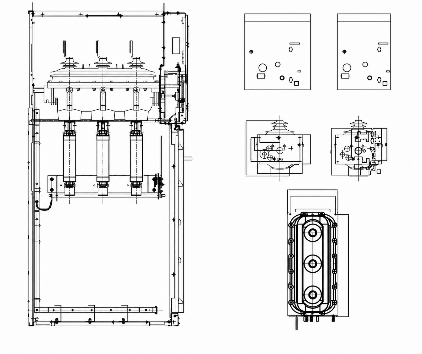
Review the rated data, operating options, phase-spacing choices, and drawing reference for this 12 kV configuration. Confirm the cabinet interface and final project options in the RFQ.
12 kV / 630 A technical parametersRated values and configuration options
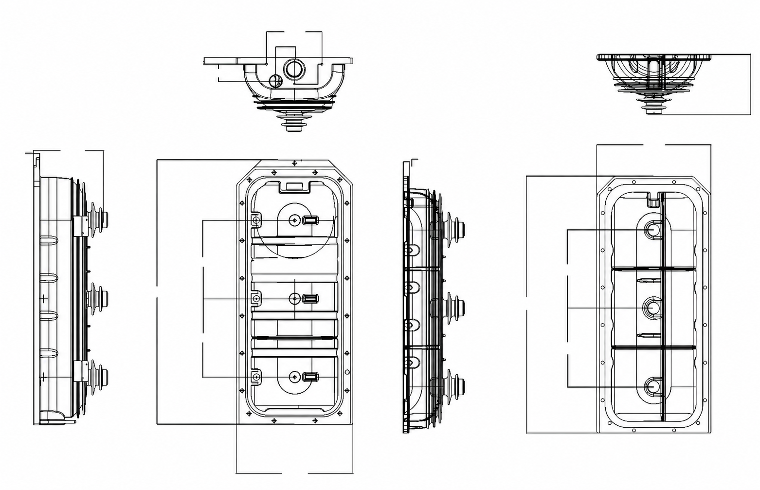
Review the rated data, electrical test values, mechanism details, and drawing for this 24 kV configuration. Confirm the cabinet interface and final project options in the RFQ.
24 kV / 630 A technical parametersRated values and configuration options
Technical parameter
Value or option
Rated voltage
24 kV
Rated current
630 A
Power-frequency withstand
65 kV / 1 min
Lightning impulse withstand
125 kV
Partial discharge
28.8 kV, less than or equal to 5 pC
Copper surface finish
Silver plated, 3 micrometres; no oxidation.
Nitrogen leak test
2 x 10^5 Pa for 3 min, no leakage.
Induced capacitance
18 plus or minus 3 pF
Reference model schedule
FLN36-24 / FLRN36-24; confirm model before specification
Rated frequency
50 Hz
Mechanical life
2,000 operations
Cable-charging breaking current
10 A
Rated transfer current
1,700 A
SF6 rated / maximum pressure at 20 C
0.04 MPa / 0.045 MPa gauge
Annual leakage rate
0.5% per year
Opening / closing synchronicity
less than or equal to 3 ms
Circuit resistance
less than or equal to 100 micro-ohm
Engineering drawing
Configuration details
35 kV SF6 load break switch layout
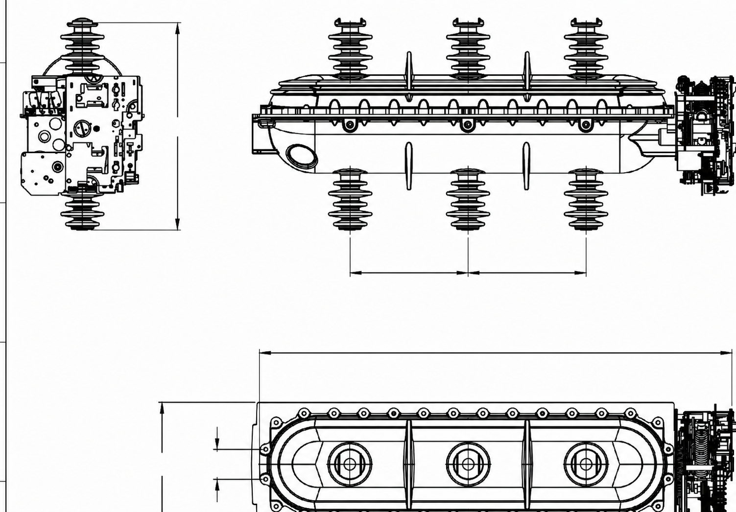
Review the dimensional envelope and manufacturing notes for this 35 kV configuration. Include the required electrical ratings, duty, and cabinet interface when requesting a complete quotation.
35 kV / drawing family technical parametersRated values and configuration options
Technical parameter
Value or option
Drawing voltage family
35 kV
Configuration scope
Dimensional envelope and manufacturing requirements
Electrical performance schedule
Confirm the required rated electrical performance in the RFQ