Send the request type, manufacturer, equipment model/year, part reference, ratings, quantity, destination, required date, and any drawing or photo notes. The SUVELL team will review the request.
Email: admin@suvell.com
Phone: +86 189 6871 1705
Factory: No.208 Wei 12 Rd, Yueqing Economic Development Zone, Wenzhou, Zhejiang, China
Select by switching role and panel interface, then open each mechanism for configuration-specific duty, interlock, drive, control, mounting, and RFQ inputs.
RMU mechanism selection
GIS incoming operating mechanism
Incoming GIS feeder mechanism for load-switch operation, earthing interlock, and panel linkage.
Engineering selection item
Configuration and RFQ input
Application role
Incoming GIS feeder and load-switch mechanism
Switching function
Coordinate load switching, isolation, and earthing functions for the incoming panel
Operating sequence and interlocks
Define close-open-earth sequence, key/mechanical interlocks, and earthing logic
Drive and control
Specify manual or motor operation, control voltage, indication, and auxiliary contacts
Mechanical interface
Provide mounting face, operating shaft or linkage direction, panel depth, and clearances
RFQ inputs
GIS panel GA, single-line diagram, switching duty, quantity, destination, and project standard
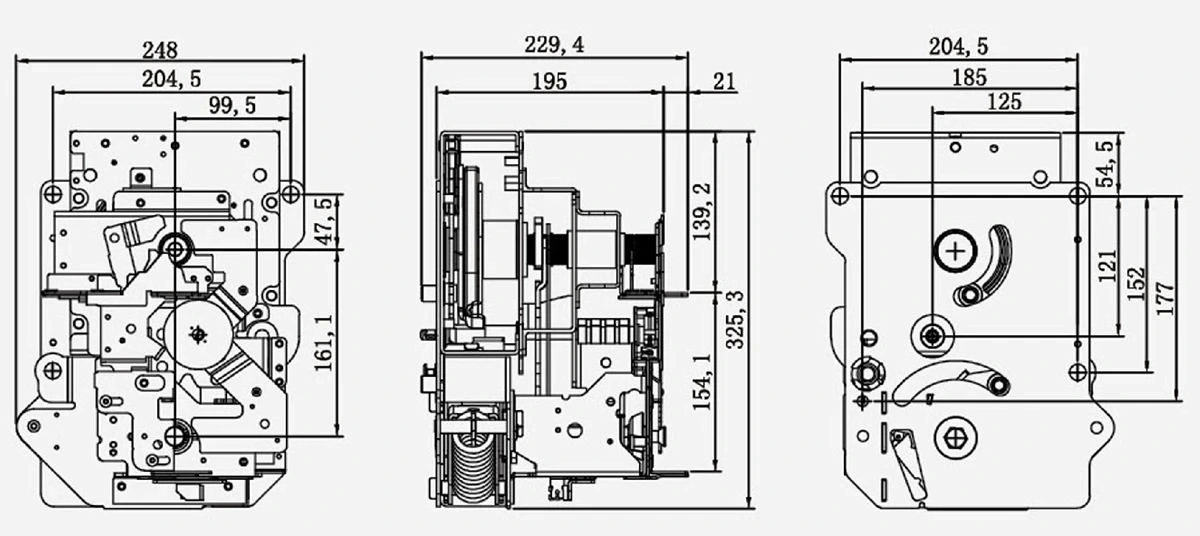
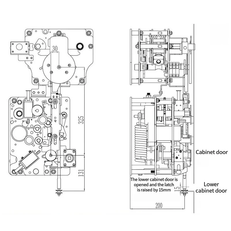
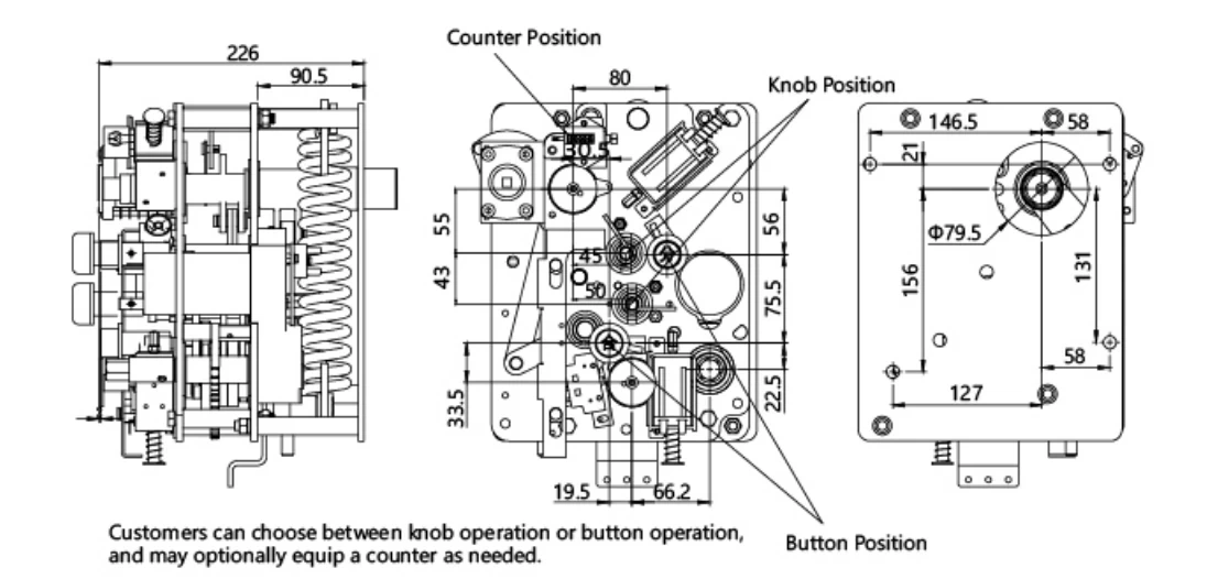
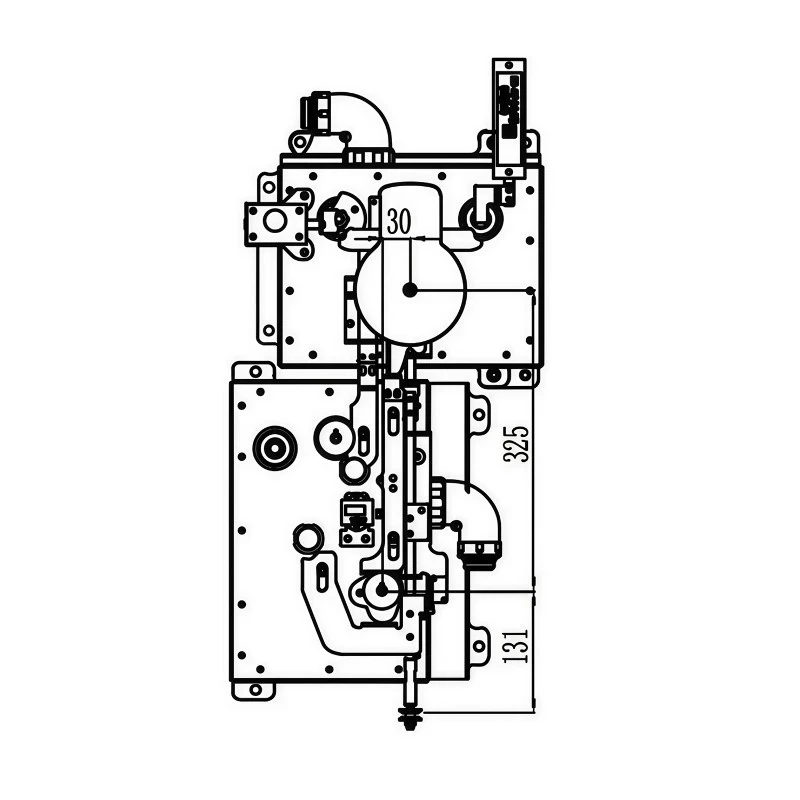
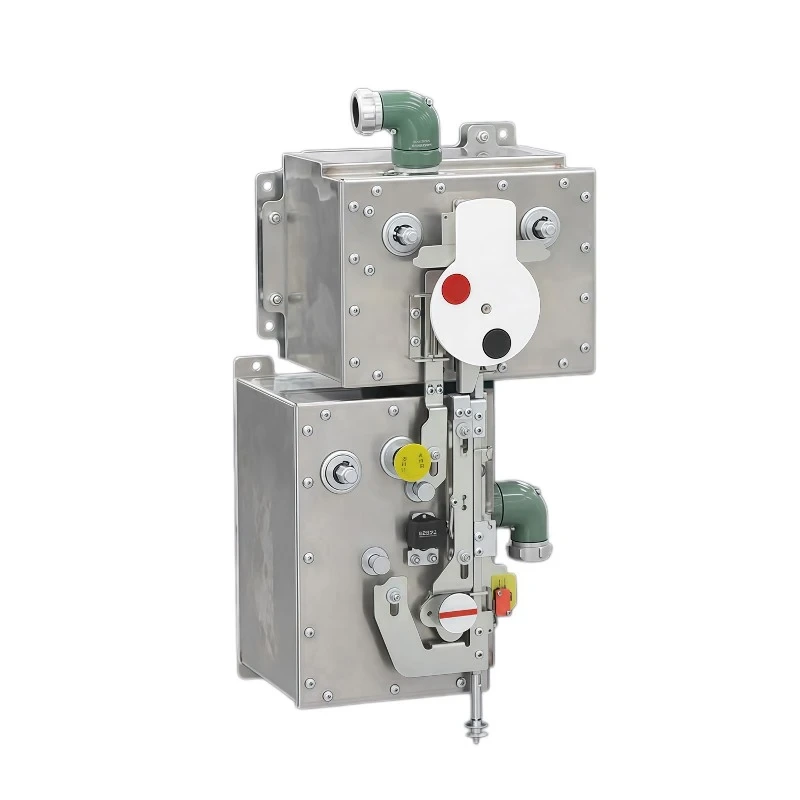
Use the full-size drawing to coordinate the general mechanism layout, operating direction, linkage points, mounting interface, and service access for the selected panel.
RMU mechanism selection
GIS outgoing operating mechanism
Outgoing GIS feeder mechanism for switching operation, earthing interlock, and panel linkage.
Engineering selection item
Configuration and RFQ input
Application role
Outgoing GIS feeder operating mechanism
Switching function
Coordinate feeder switching, isolation, and earthing functions for the outgoing panel
Operating sequence and interlocks
Define close-open-earth sequence and the required mechanical or key interlocks
Drive and control
Specify operating mode, control voltage, position indication, and auxiliary contacts
Mechanical interface
Provide panel mounting face, shaft/linkage direction, cable-side arrangement, and clearances
RFQ inputs
Outgoing panel GA, feeder duty, interlock schedule, quantity, destination, and project standard
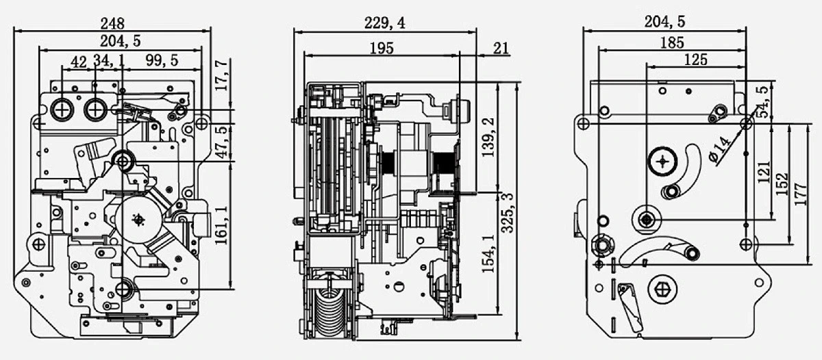
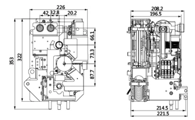
Use the full-size drawing to coordinate the general mechanism layout, operating direction, linkage points, mounting interface, and service access for the selected panel.
RMU mechanism selection
Spring operating mechanism
Spring-operated mechanism for circuit-breaker closing, tripping, interlocking, and auxiliary contacts.
Engineering selection item
Configuration and RFQ input
Application role
Stored-energy spring mechanism for vacuum circuit-breaker operation
Switching function
Define circuit-breaker closing, tripping, and protection-operating requirements
Operating sequence and interlocks
Specify close-trip sequence, anti-pumping, mechanical interlocks, and status indication
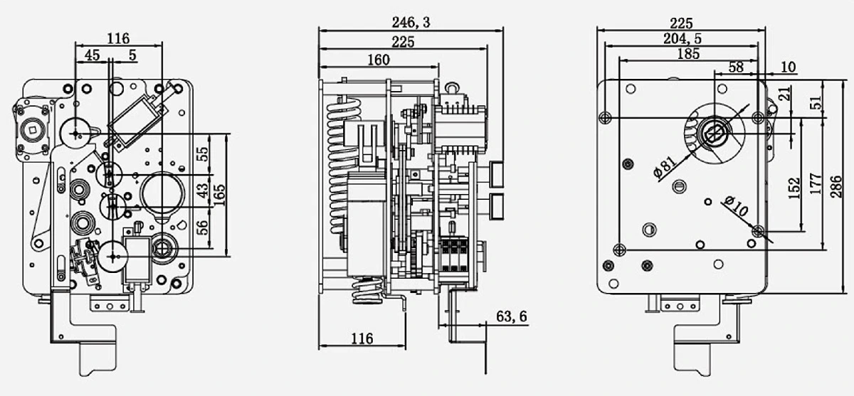
Use the full-size drawing to coordinate the general mechanism layout, operating direction, linkage points, mounting interface, and service access for the selected panel.
RMU mechanism selection
Semi-solid seal isolation mechanism
Gas-insulated isolation mechanism for sealed interfaces, panel mounting, and service access.
Engineering selection item
Configuration and RFQ input
Application role
Operating mechanism for a sealed isolation interface
Switching function
Define isolation and earthing functions required by the sealed switchgear compartment
Operating sequence and interlocks
Specify isolator/earthing sequence, access interlocks, and position indication
Drive and control
State manual or motor operation, control supply, indication, and auxiliary-contact schedule
Mechanical interface
Provide seal interface, mounting face, linkage route, enclosure geometry, and service access
Use the full-size drawing to coordinate the general mechanism layout, operating direction, linkage points, mounting interface, and service access for the selected panel.
Mechanism detail view
RMU mechanism selection
Outgoing line operating mechanism
Line-switching mechanism for close-open-earth operation, interlocking, and panel mounting.
Engineering selection item
Configuration and RFQ input
Application role
Outgoing line switching and earthing mechanism
Switching function
Coordinate feeder close-open-earth operation for the outgoing cable circuit
Operating sequence and interlocks
Define operating order, earthing permissive, door interlock, and position indication
Drive and control
Specify manual/motor drive, control voltage, terminal interface, and auxiliary contacts
Mechanical interface
Provide mounting face, shaft/linkage direction, cable-compartment arrangement, and clearances
RFQ inputs
Outgoing circuit duty, panel GA, interlock logic, control schematic, quantity, and destination
Use the full-size drawing to coordinate the general mechanism layout, operating direction, linkage points, mounting interface, and service access for the selected panel.
Mechanism detail view
RMU mechanism selection
Spring circuit-breaker mechanism
Spring mechanism for circuit-breaker duty with closing, tripping, control, and auxiliary interfaces.
Engineering selection item
Configuration and RFQ input
Application role
Spring-charged mechanism for RMU circuit-breaker duty
Switching function
Define breaker closing/tripping duty and coordination with the protection system
Operating sequence and interlocks
Specify operating sequence, trip-free/anti-pumping needs, and panel interlocks
Drive and control
State charging motor and close/trip coil voltage, manual backup, indication, and contacts
Mechanical interface
Provide breaker shaft/linkage, mounting pattern, operating travel, and maintenance clearance
RFQ inputs
Breaker type, duty and sequence, control diagram, panel drawing, quantity, and destination
Use the full-size drawing to coordinate the general mechanism layout, operating direction, linkage points, mounting interface, and service access for the selected panel.
Mechanism detail view
RMU mechanism selection
Spring incoming-line mechanism
Incoming-feeder spring mechanism for stored-energy drive, switching duty, and control interlocks.
Engineering selection item
Configuration and RFQ input
Application role
Stored-energy mechanism for an incoming RMU feeder
Switching function
Define the incoming feeder switching and isolation duty for the selected panel
Operating sequence and interlocks
Specify close-open-earth sequence, upstream/downstream interlocks, and indication
Drive and control
State spring charging method, control voltage, remote/local operation, and contacts
Mechanical interface
Provide incoming panel mounting face, linkage direction, shaft position, and clearances
RFQ inputs
Incoming circuit duty, SLD, panel GA, control requirement, quantity, and delivery destination
Use the full-size drawing to coordinate the general mechanism layout, operating direction, linkage points, mounting interface, and service access for the selected panel.
Mechanism detail view
RMU mechanism selection
IP67 outdoor RMU mechanism
Outdoor RMU mechanism for IP67 enclosure applications, panel mounting, and site conditions.
Engineering selection item
Configuration and RFQ input
Application role
Outdoor RMU operating mechanism for an IP67 enclosure arrangement
Switching function
Define load switching, isolation, earthing, or breaker operation for the outdoor panel
Operating sequence and interlocks
Specify sequence, access/earthing interlocks, lockout, and position indication
Drive and control
State manual or motor operation, control supply, external indication, and contacts
Mechanical interface
Provide enclosure interface, external handle/shaft position, sealing points, and mounting pattern
RFQ inputs
Outdoor panel drawing, site conditions, ingress-protection requirement, quantity, and destination
Use the full-size drawing to coordinate the general mechanism layout, operating direction, linkage points, mounting interface, and service access for the selected panel.
Mechanism detail view
Project engineering
RMU MechanismProject Inputs
Define the switchgear interface, switching duty, operating sequence, drive and control circuit, interlocks, site conditions, and delivery requirements before quotation.
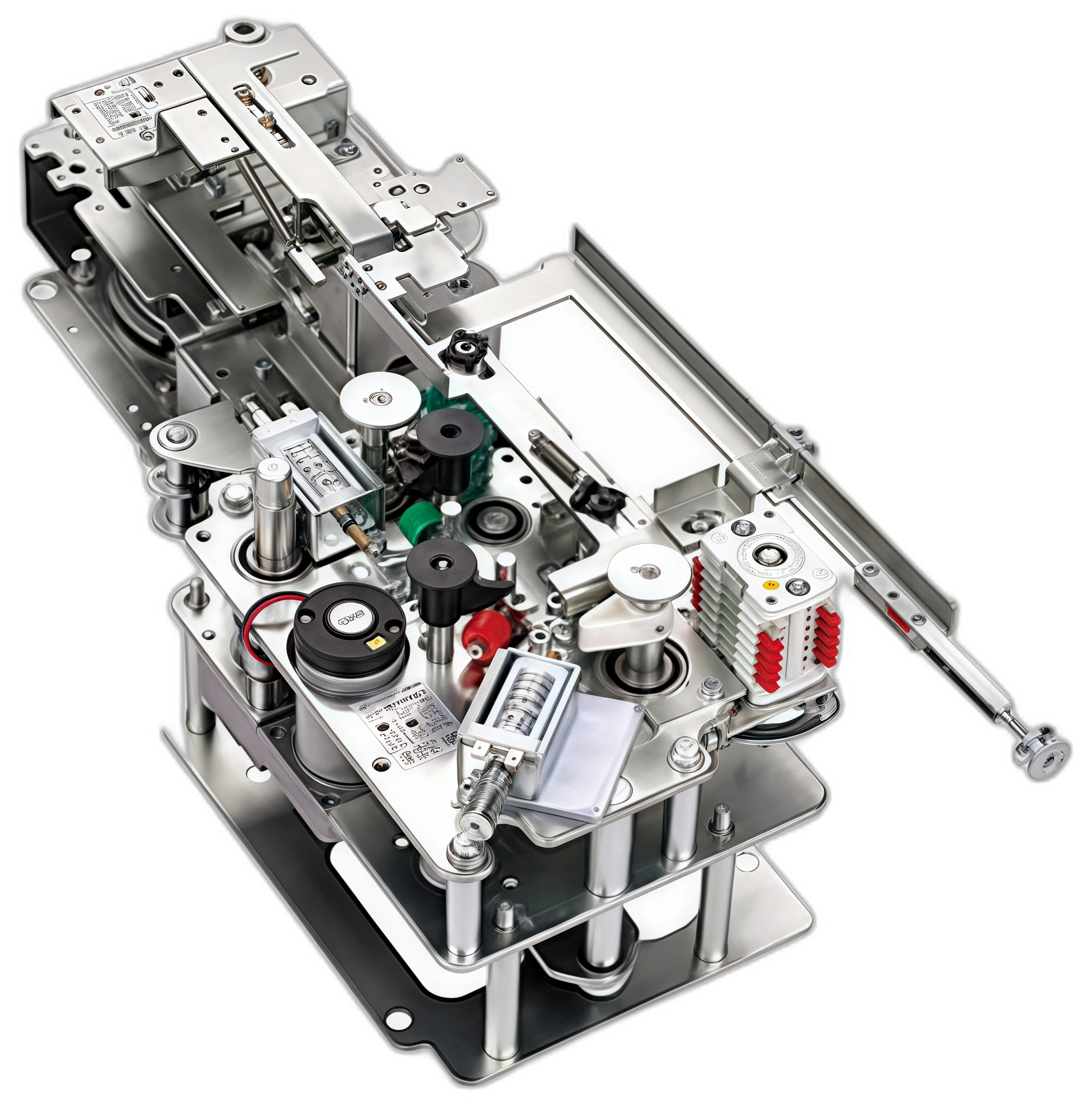
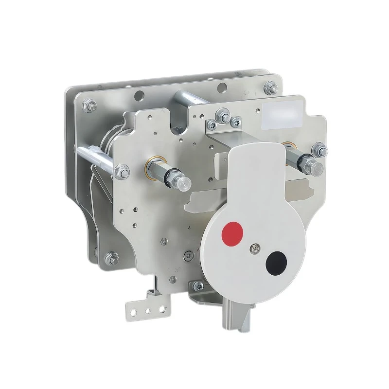
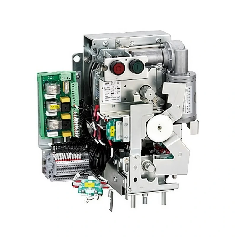
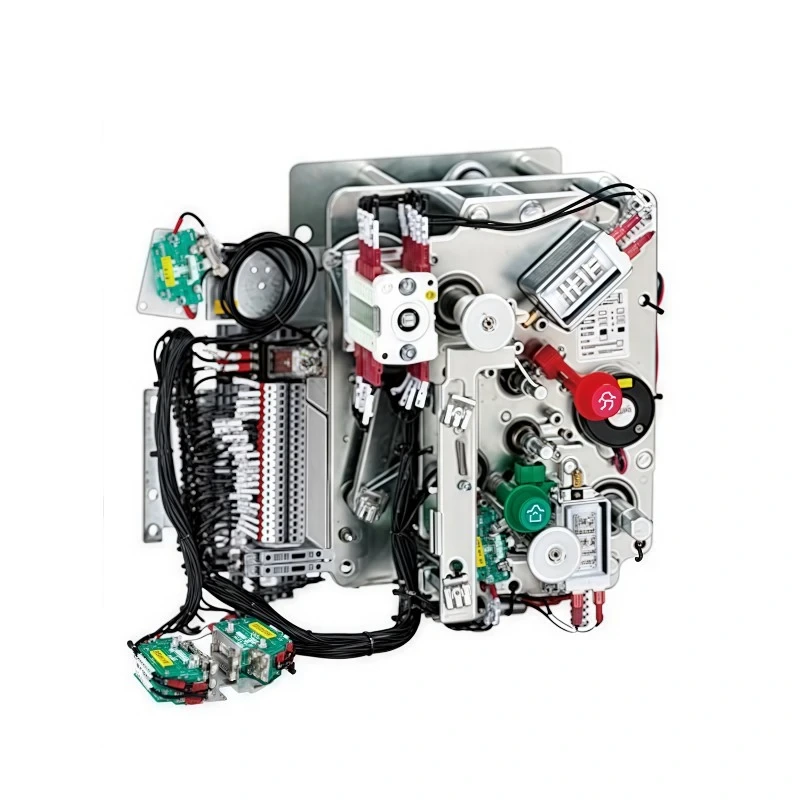
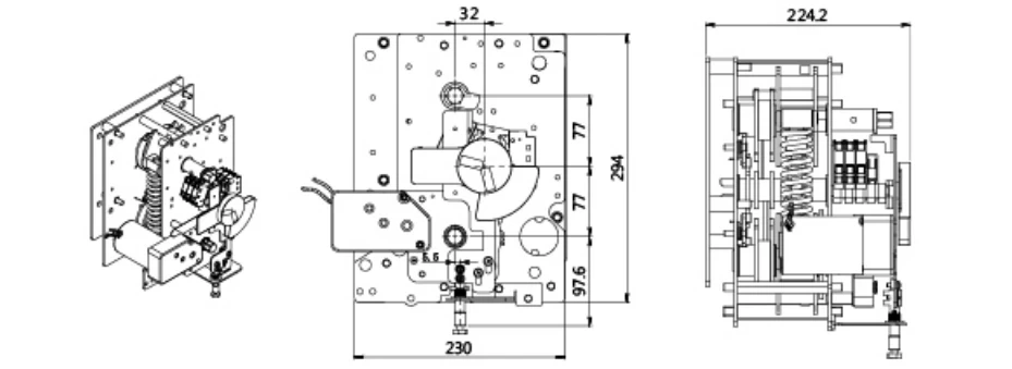
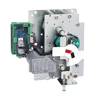
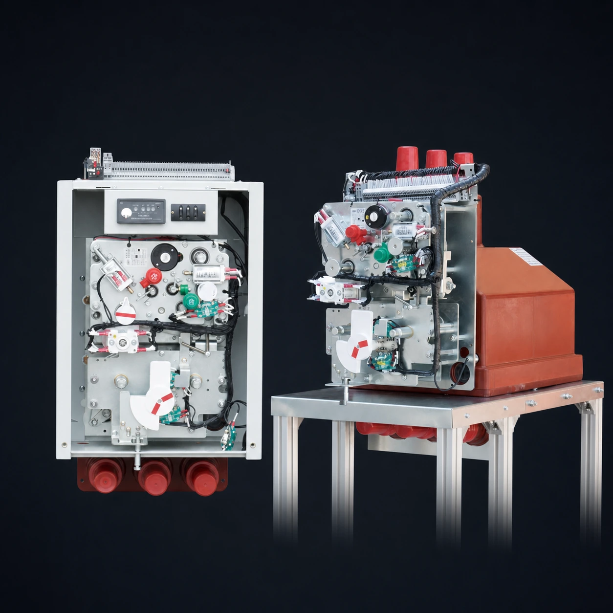
RMU mechanism and control-interface views for coordinating mounting, linkage, operating access, terminals, indication, and auxiliary contacts.
Define the mechanism interface
Panel and mounting interface
Send the switchgear type, mounting face, linkage direction, and available operating clearance.
Switching sequence and interlocks
State the switching function, close-open-earth sequence, mechanical interlocks, and any earthing requirement.
Control circuit and auxiliary contacts
Specify the control voltage, charging method, terminal interface, auxiliary contacts, and required indication.
Proposal output
Quotation-ready engineering brief
Send the application, panel layout, switching sequence, control requirements, quantity, and destination so the mechanism configuration and drawing scope can be prepared for quotation.
Custom mounting, marking, interfaces, and component integration for your switchgear build.
Documentation and quality
Inspection, traceability, and documentation deliverables aligned with the order requirement.
Packing and delivery
Quantity, destination, packing requirement, and delivery terms prepared for quotation.
Related components
Related RMUComponents
Continue from the operating mechanism to the switching, protection, and insulation interfaces that define a complete RMU panel.
RMU Mechanism FAQ
RMU MechanismTechnical FAQ
Use these checkpoints to distinguish mechanism duty and prepare a complete RMU operating mechanism enquiry.
What information is needed to select an RMU operating mechanism?
Provide the RMU application, switching function, panel general arrangement, mounting face, linkage or shaft direction, operating sequence, interlocks, control voltage, auxiliary contacts, quantity, and destination.
How do I distinguish load-switch, isolation, and circuit-breaker mechanisms?
Start with the switching duty and operating sequence. Then coordinate the drive type, earthing function, interlocks, control circuit, shaft or linkage interface, panel clearances, and the selected switch or breaker.
Can an RMU mechanism be matched to an existing panel?
Suvell can assess a compatible mechanism or adaptation from the panel layout, mounting face, shaft or linkage direction, operating clearance, interlock logic, and available mechanism photographs or drawings.
What should be included in an RMU mechanism RFQ?
Send the single-line diagram and panel drawing, switching duty, operating sequence, interlocks, control voltage, auxiliary-contact schedule, site conditions, quantity, destination, and any existing nameplate or mechanism photographs.
Project inquiry
RMU MechanismProject RFQ
Send the switching duty, panel and mounting interface, operating sequence, interlocks, control requirements, site conditions, quantity, and destination.
Send the essentials
Panel GA, mounting face, and linkage directionSwitching duty, sequence, and interlocksDrive type, control voltage, and auxiliary contactsSite conditions and ingress-protection requirementQuantity, destination, packing, and delivery termsSingle-line diagram, nameplate, or mechanism photos