Transformer voltage regulation components

Off-load Transformer Tap Changers

Compare linear and oil-immersed rotary off-load tap changers for de-energized transformer voltage adjustment. Select by winding and phase arrangement, rated through-current, tap range and positions, connection sequence, tank-cover mounting and operating interface.

Off-load transformer tap changer for de-energized voltage adjustment
Off-load tap changer selection

Off-load Tap Changer Configurations

Choose the linear or rotary configuration, then review the visible electrical duty, tap-position arrangement, transformer connection, mounting interface and engineering drawings before preparing the RFQ.

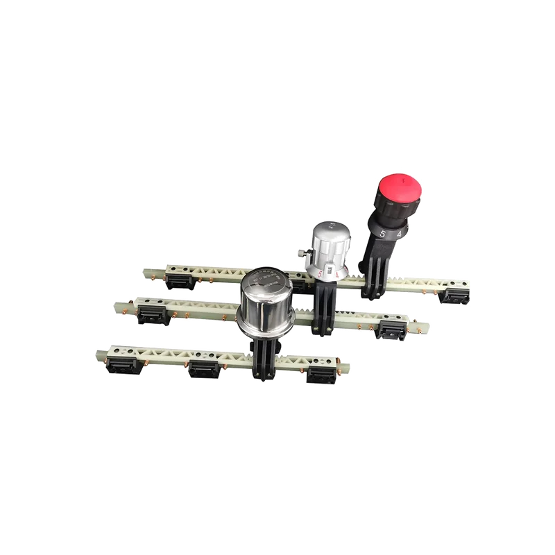
Off-load Linear Tap Changers product view
Product path 01

Off-load Linear Tap Changers

Three-phase linear tap changer configurations for off-circuit voltage adjustment, compared by rated through-current, insulation level, terminal arrangement and transformer interface.

Review technical data and drawings →

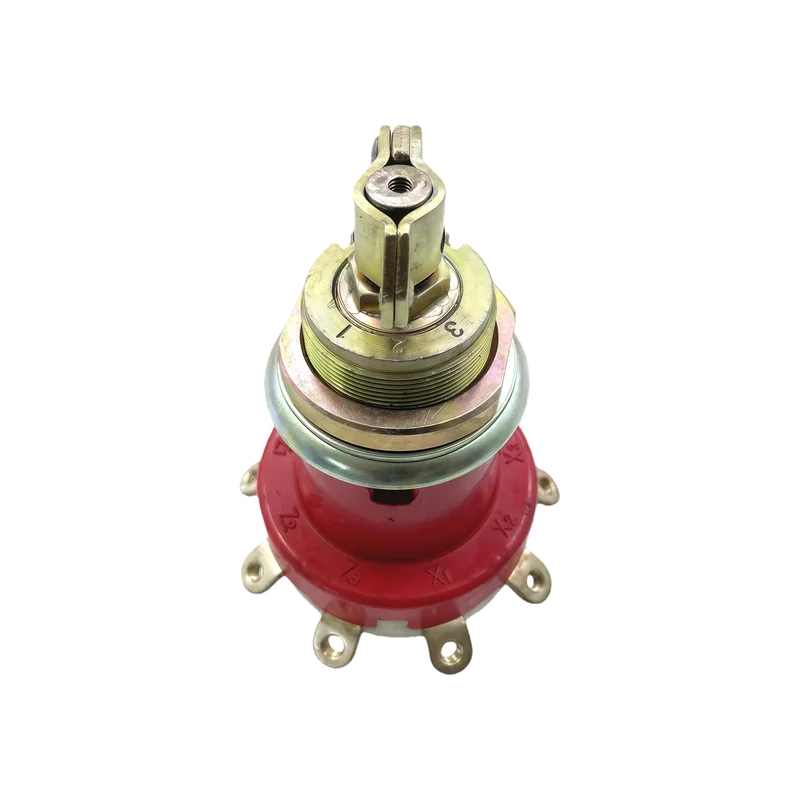
Oil-immersed Rotary Single-phase Tap Changers product view
Product path 02

Oil-immersed Rotary Single-phase Tap Changers

Oil-immersed single-phase rotary configurations selected by tap positions, contact sequence, shaft and handle arrangement, tank-cover mounting and available clearances.

Review technical data and drawings →

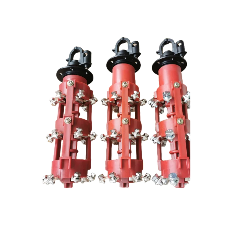
Oil-immersed Rotary Three-phase Tap Changers product view
Product path 03

Oil-immersed Rotary Three-phase Tap Changers

Oil-immersed three-phase rotary configurations compared by voltage and current duty, tap-position arrangement, terminal configuration, drawings and tank-cover interface.

Review technical data and drawings →

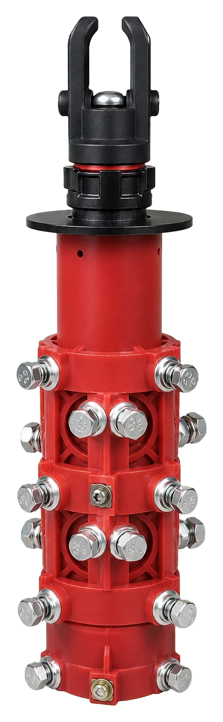
Three-phase Five-position Rotary Tap Changers product view
Product path 04

Three-phase Five-position Rotary Tap Changers

Three-phase five-position rotary configurations for off-circuit tap selection, coordinated with the transformer winding connection, operating handle and installation drawing.

Review technical data and drawings →

Linear off-load tap changer

Off-load Linear Tap Changers

Review the visible configuration data and drawings, then coordinate the transformer duty, tap winding, connection sequence, tank-cover mounting, operating clearances and order documents.

On small screens, scroll the table horizontally.

Technical parameter WST 30 WST 63 WST 125
Phase number Three-phase
Connection mode Central point
Rated through current (A) 30 63 125
Short-circuit capacity Rated short-time withstand current (kA / 2 s) 0.7 1.6 2.5
Rated peak withstand current (kA) 1.8 4 6.25
Rated frequency (Hz) 50~60
Insulation level (kV) Rated voltage (kV) 10 kV 20 kV 35 kV
Power-frequency withstand voltage (50 Hz / 1 min) 42 kV 55 kV 95 kV
Lightning impulse withstand voltage (1.2/50 μs) 75 kV 125 kV 250 kV
Sealing performance (kPa / 24 h) 60
Mechanical endurance (thousand operations) 2

Request this tap changer configuration

Single-phase rotary tap changer

Oil-immersed Rotary Single-phase Tap Changers

Review the visible configuration data and drawings, then coordinate the transformer duty, tap winding, connection sequence, tank-cover mounting, operating clearances and order documents.

Engineering drawings

Dimensional and Interface Views

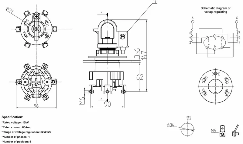
Oil-immersed Rotary Single-phase Tap Changers engineering drawing 1
Engineering drawing 1

Use these views with the transformer connection, tank-cover mounting and selected tap changer configuration.

On small screens, scroll the table horizontally.

Technical parameter / selection item Configuration / value
Product family Oil-immersed rotatable single-phase
Technical parameter table Confirm for the selected configuration
Phase arrangement Single-phase
Tap positions and contact sequence Customizable
Mounting arrangement and clearances Customizable
Drawing and installation inputs Required for configuration review

Request this tap changer configuration

Three-phase rotary tap changer

Oil-immersed Rotary Three-phase Tap Changers

Review the visible configuration data and drawings, then coordinate the transformer duty, tap winding, connection sequence, tank-cover mounting, operating clearances and order documents.

Engineering drawings

Dimensional and Interface Views

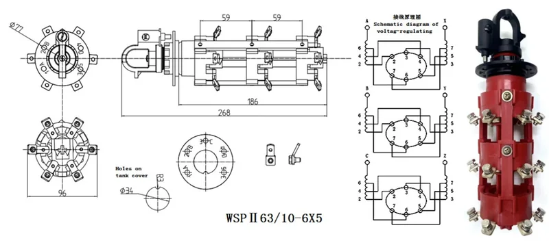
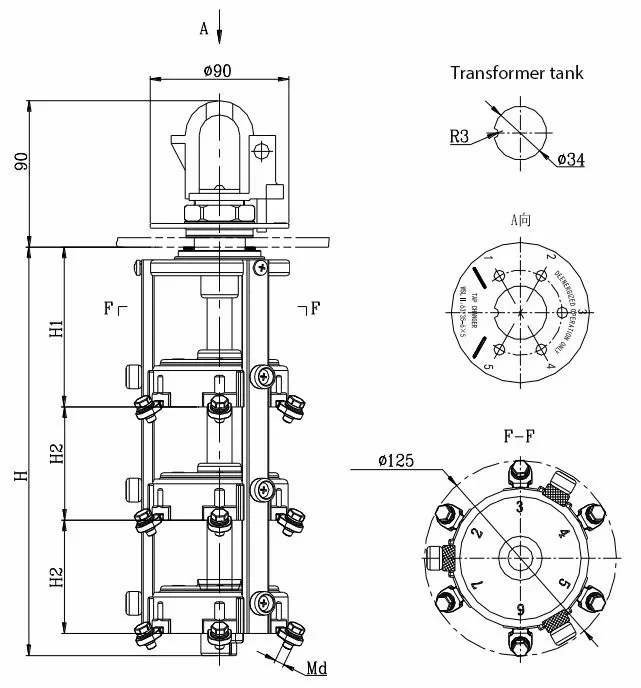
Oil-immersed Rotary Three-phase Tap Changers engineering drawing 1
Engineering drawing 1
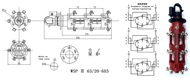
Oil-immersed Rotary Three-phase Tap Changers engineering drawing 2
Engineering drawing 2
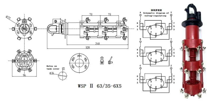
Oil-immersed Rotary Three-phase Tap Changers engineering drawing 3
Engineering drawing 3

Use these views with the transformer connection, tank-cover mounting and selected tap changer configuration.

On small screens, scroll the table horizontally.

Technical parameter / selection item Configuration / value
Voltage classes 15 / 25 / 35 kV
Rated current 63 / 125 A
Product family Oil-immersed rotatable three-phase
Model / terminal configuration Customizable — confirm against project drawing
Tap positions and connection sequence Customizable
Drawing and installation inputs Required for configuration review

Request this tap changer configuration

Five-position rotary tap changer

Three-phase Five-position Rotary Tap Changers

Review the visible configuration data and drawings, then coordinate the transformer duty, tap winding, connection sequence, tank-cover mounting, operating clearances and order documents.

Engineering drawings

Dimensional and Interface Views

Three-phase Five-position Rotary Tap Changers engineering drawing 1
Engineering drawing 1

Use these views with the transformer connection, tank-cover mounting and selected tap changer configuration.

On small screens, scroll the table horizontally.

Technical parameter / selection item Configuration / value
Tap settings +5% / +2.5% / 0 / −2.5% / −5%
Voltage options 10 / 20 / 35 kV
Product family 3P five-position oil-immersed rotary
Phase arrangement Three-phase
Rotary operating handle and tank-cover interface Customizable
Drawing and installation inputs Required for configuration review

Request this tap changer configuration

Engineering coordination

Confirm Tap Changer Project Inputs

Coordinate the electrical duty, tap winding, phase arrangement, number of service positions, tank-cover interface, operating access, drawings, inspection documents and delivery scope before quotation and manufacture.

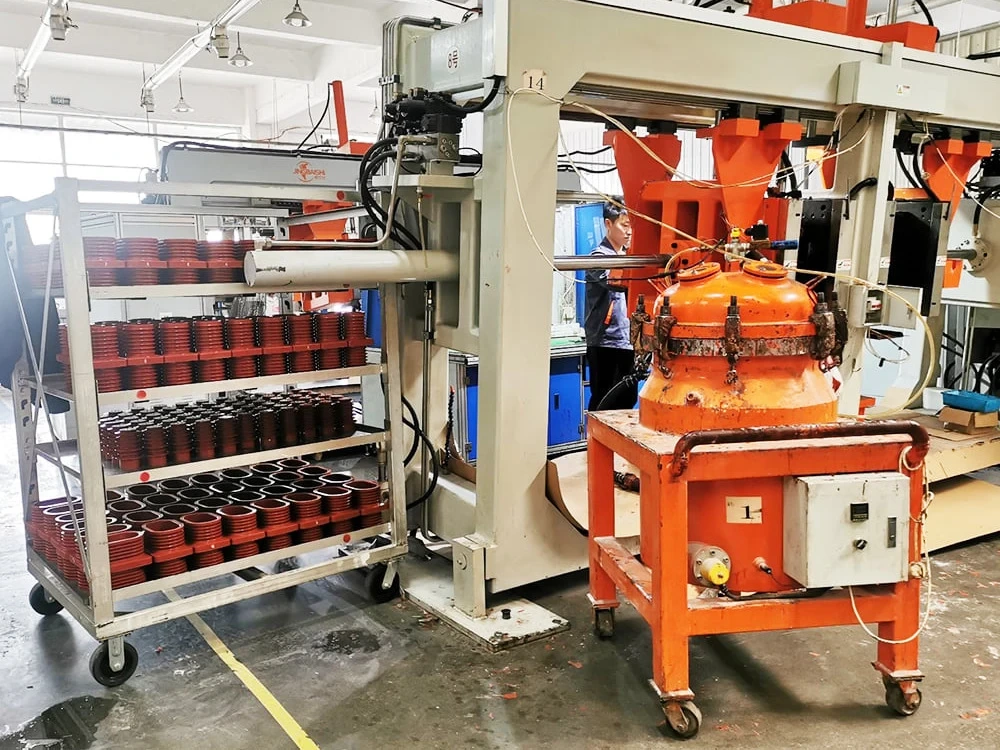
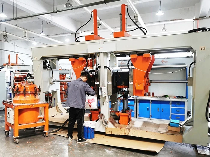
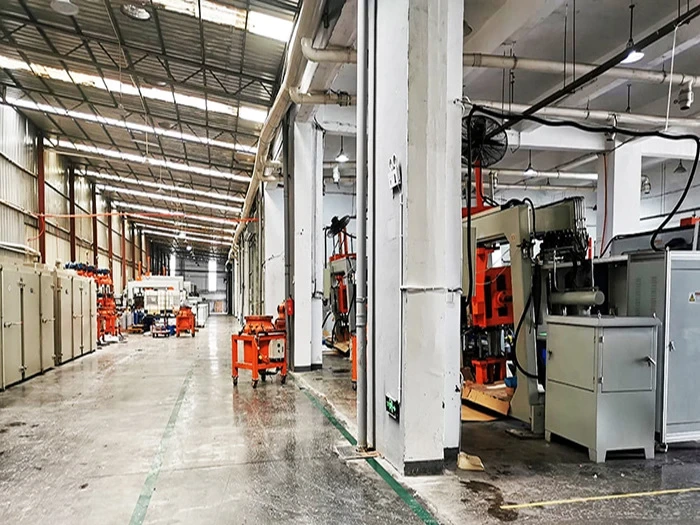
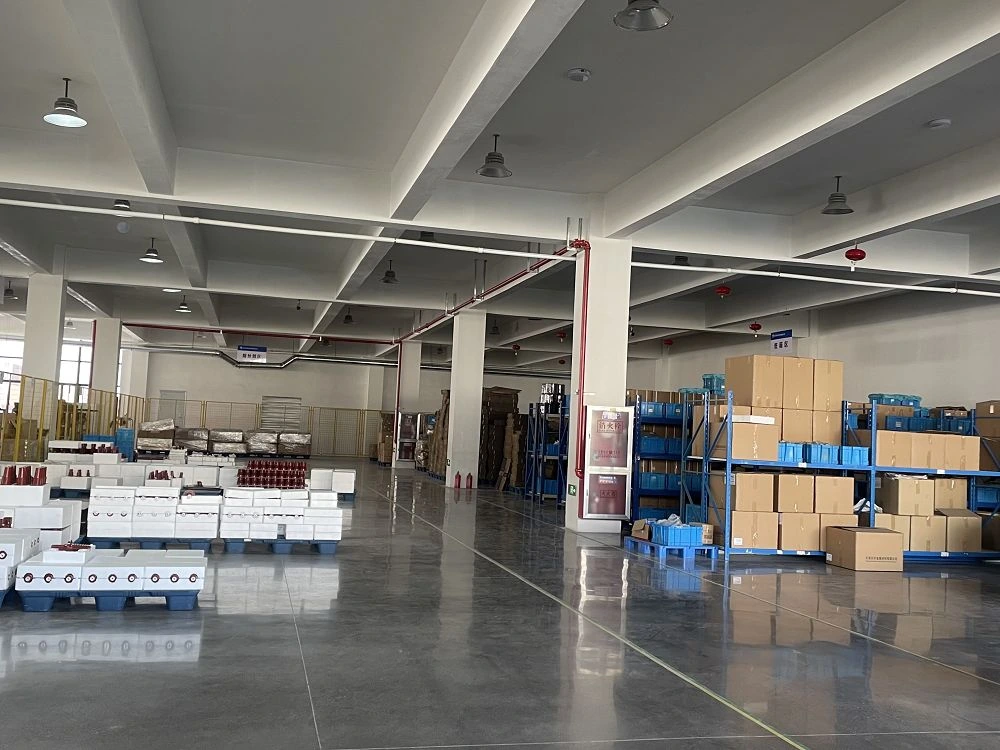
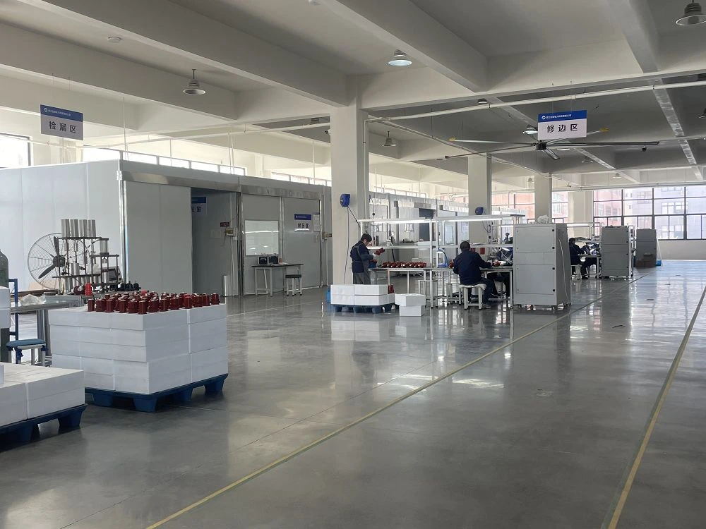
Transformer component workshop operation
Transformer component assembly process
Production and deliveryCoordinate inspection, packing and shipment requirements.

Define inspection steps, product identification, protective packing, shipment documents and dispatch requirements for the selected configuration.

Transformer component production line
Transformer component preparation and packing area
Preparation and packing area
Transformer component inspection and assembly area
Inspection and assembly area

Coordinate electrical, mechanical and commercial inputs.

Electrical operating duty

Confirm transformer kVA or MVA, winding and phase arrangement, rated through-current, frequency, tap range, step voltage and required service positions.

Installation and operating interface

Provide tank-cover mounting, shaft length, handle direction, terminal layout, contact sequence, operating clearance and the de-energized operating arrangement.

Drawing and order scope

Include applicable GA or interface drawings, connection sequence, marking, inspection documents, packing, quantity, destination and requested delivery timing.

OEM / ODM configuration

Coordinate phase arrangement, tap positions, connection sequence, terminals, shaft or handle, mounting and marking with the transformer design.

Inspection and documents

Define inspection, test records, traceability, drawings, configuration sheets and shipment-document requirements for the order.

Packing and delivery

State quantity, destination, packing method, logistics constraints, consignee details and requested dispatch schedule.

Specification-to-delivery workflow

Tap Changer Specification to Delivery

Move the selected linear or rotary configuration through technical confirmation, production planning, assembly, inspection, packing and dispatch with one controlled set of order inputs.

  1. 01

    Technical confirmation

    Confirm tap changer family, transformer duty, phase, positions, connection sequence, mounting and drawings.

  2. 02

    Configuration and planning

    Align terminals, shaft or handle, materials, marking, quantity, inspection scope and delivery window.

  3. 03

    Production preparation

    Prepare the selected configuration, production route, work instructions and order identification.

  4. 04

    Assembly coordination

    Assemble the contact, mechanism, terminals and operating interface to the confirmed configuration.

  5. 05

    Inspection and packing

    Complete the specified checks, records, product identification, protective packing and shipment documents.

  6. 06

    Dispatch and delivery

    Confirm destination, logistics method, consignee details and the planned dispatch schedule.

Discuss tap changer production and delivery →

Engineering selection FAQ

Off-load Tap Changer Selection FAQ

Use these answers to compare linear and rotary configurations, understand de-energized operation and prepare the electrical, mounting and drawing inputs for selection.

What information is needed to select an off-load tap changer?

Provide the transformer rating, winding and phase arrangement, rated through-current, required tap range and service positions, connection sequence, tank-cover mounting, shaft or handle orientation, available clearances, drawings or photos, quantity and destination.

What is the difference between linear and rotary off-load tap changers?

A linear tap changer uses a linear contact and terminal arrangement, while a rotary tap changer uses a rotating contact mechanism. Select the family from the transformer winding connection, phase arrangement, tap positions, current duty, mounting interface and operating-access requirements.

Can an off-load tap changer be operated while the transformer is energized?

An off-load or de-energized tap changer is intended for tap changes only after the transformer has been de-energized and isolated. Follow the equipment operating instructions, interlocking arrangement and site safety procedure before changing position.

Which mounting and connection details should be checked?

Check the tank-cover opening and mounting pattern, shaft length and handle direction, terminal or lead layout, contact sequence, tap winding connection, operating clearance, oil-side arrangement and the applicable dimensional drawing.

Can the tap changer configuration be customized for an OEM transformer project?

Phase arrangement, tap positions, terminal layout, shaft or handle configuration, mounting, marking, inspection documents, packing and delivery scope can be reviewed against the transformer drawing and order requirements.

Off-load tap changer RFQ

Request Tap Changer Engineering Support

Share the transformer duty, tap winding, required positions, connection and mounting interface so SUVELL can review the configuration and quotation scope.

Useful project inputs

Transformer kVA/MVA, voltage, frequency and winding arrangementRated through-current, tap range, step voltage and service positionsLinear or rotary family, phase arrangement and connection sequenceTank-cover mounting, shaft or handle, terminals and clearancesDrawings, nameplate, photos, marking and required documentsQuantity, destination, packing and requested delivery timing

Send tap changer RFQ →