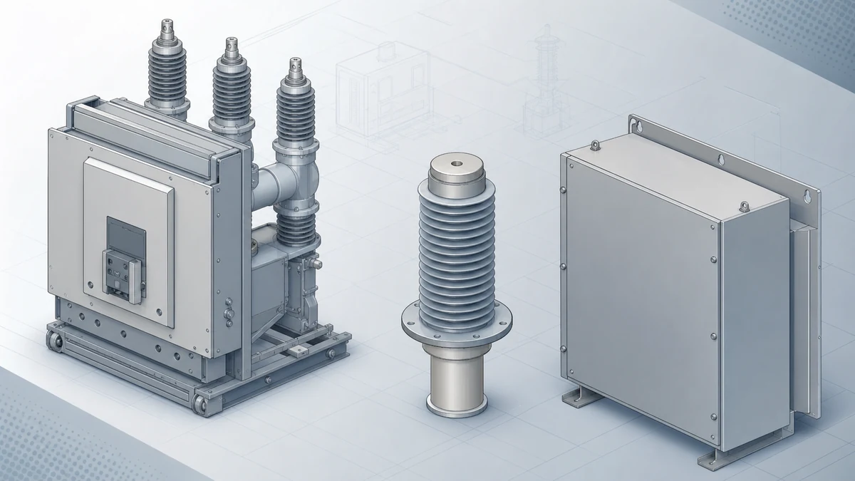
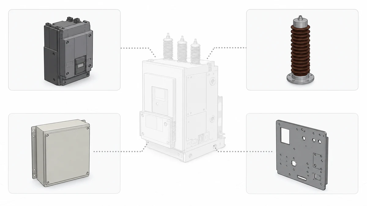
Send the request type, manufacturer, equipment model/year, part reference, ratings, quantity, destination, required date, and any drawing or photo notes. The SUVELL team will review the request.
Email: admin@suvell.com
Phone: +86 189 6871 1705
Factory: No.208 Wei 12 Rd, Yueqing Economic Development Zone, Wenzhou, Zhejiang, China
What Drawings, Photos, and Nameplate Data Make a Replacement-Part RFQ Actionable?
An actionable replacement-part RFQ combines ratings with evidence of mechanical fit and control-circuit integration. This guide sets out the drawings, photographs, connector details, and auxiliary-circuit information suppliers need, while showing how to flag site modifications and documentation gaps before a replacement is approved.
Pair current arrangement and control drawings with photographs of the nameplate, installed mounting, secondary connector, and compartment.
State the full equipment variant, primary ratings, operating duty, and separate trip-coil, close-coil, and motor supply requirements.
Document fixed or withdrawable interfaces, auxiliary contact assignments, and site modifications, and flag any missing evidence for engineering review.
A replacement electrical part RFQ becomes actionable only when it carries enough evidence for an engineer to confirm mechanical fit, electrical compatibility, and control-circuit integration without revisiting the site. Nameplate data is necessary but not sufficient — ABB's documentation for the VD4 series explicitly separates the rating plate from the operating mechanism, auxiliary equipment, and interlocks as distinct technical features, each requiring independent verification. Schneider Electric's HVX integration guidance similarly treats mechanical fixation, earthing, primary interfaces, auxiliary wiring, racking, shutters, and door interlocking as separate interface groups, any one of which can block a direct replacement.
The checklist below structures the evidence package around those interface groups. Follow it before submitting any RFQ, and treat each section as a gate: missing data in one group cannot be compensated by detail in another.
Why a Nameplate Alone Cannot Close an RFQ
The rating plate establishes electrical duty — voltage, current, breaking capacity, frequency, and insulation level. Those values matter, but they describe what the device must withstand, not how it connects to the switchgear it lives in.
ABB's VD4 service documentation draws a hard line between fixed and withdrawable versions of the same breaker family. A fixed-mount unit and a withdrawable cradle unit may share identical rating plate values yet differ entirely in their mechanical interface, racking geometry, shutter actuation, and secondary plug configuration. Quoting from nameplate data alone against the wrong variant produces a part that meets every electrical specification and fits nothing.
The control circuit adds a second layer. Auxiliary switches, motor-charged spring indicators, anti-pumping relays, and trip coil supervision circuits are listed separately from the main breaking mechanism in ABB's documentation because they are separately configurable. A replacement ordered to match only the nameplate may arrive with the wrong number of auxiliary contacts, contacts on the wrong normally-open/normally-closed assignment, or a spring charge motor wound for a different control voltage.
Schneider's HVX integration guidance reinforces this by cataloguing door interlocking and racking as independent interface groups. Both features involve mechanical sequences that must be reproduced in the replacement. A breaker that cannot complete its racking stroke without binding, or that breaks the door interlock chain, creates a maintenance hazard regardless of its electrical ratings.
The practical rule: nameplate data opens the search; drawings and photographs close it.
The Evidence Package — Drawings
Drawings are the primary source for dimensional and interface data. Collect the following before the RFQ is written.
**General arrangement drawing.** The GA drawing establishes the overall envelope, mounting bolt pattern, and the relationship between the breaker chassis and the cubicle. For withdrawable gear, it also shows the cradle or truck geometry and the racking-in depth. Without it, a supplier cannot confirm whether the replacement unit clears the enclosure walls, bus barriers, or adjacent equipment.
**Secondary wiring diagram (control schematic).** This drawing must cover all auxiliary circuits: trip coil, close coil, anti-pumping, spring charge motor, position contacts, and any interlocking relays. The diagram should include terminal designations so that wiring continuity can be confirmed after installation. Replacing a breaker without this document means the control circuit has to be reconstructed from the existing wiring — a time-consuming process that introduces transcription errors.
**Cubicle or switchboard layout drawing.** Where the breaker sits within a multi-compartment switchboard affects bus bar clearances, cable termination lengths, and the path of any control cable harness. A breaker that is dimensionally correct in isolation may reduce creepage or clearance distances when installed in the actual compartment.
**Interlock and racking sequence diagram.** For withdrawable designs, the racking sequence is a mechanical logic chain. Schneider's HVX guidance categorises shutters and door interlocking as separate interface groups precisely because both must function through the full insert-test-service stroke. A diagram showing the shutter actuation geometry and the door interlock cam positions gives a supplier the information needed to match the mechanical cam profile of the replacement unit.
**As-built drawings, where they differ from issued-for-construction versions.** Site modifications — added auxiliary contacts, changed wiring routes, relocated relays — are frequently marked up on paper and never formally revised. Submitting only the original design drawing while the site runs to a different configuration produces an RFQ that describes a unit that no longer matches what is installed.
The Evidence Package — Photographs
Photographs capture the physical state of the installation and the existing part in a way drawings cannot. They document wear, modifications, and configuration choices that are rarely recorded elsewhere.
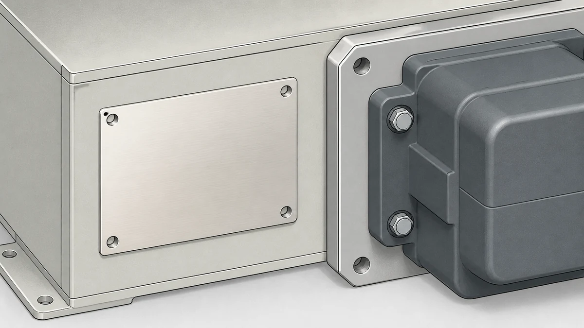
**Nameplate photograph, full frame and legible.** The nameplate image must be sharp enough to read every field: manufacturer, type designation, serial number, rated voltage, rated current, rated breaking capacity, rated operating sequence, control voltage, and any suffix codes that denote variant configurations. A photograph is more reliable than a manual transcription because it preserves characters that are easily confused in handwriting (B/8, 0/O, 1/I) and captures codes that the person on site may not recognise as significant.
**Existing part in situ, showing its orientation and mounting.** This photograph confirms the mounting arrangement (fixed or withdrawable), the direction of cable entry, the orientation of the busbar connections, and whether the unit is in a standalone cubicle or a multi-tier arrangement. It also documents the actual cable termination hardware, which matters if the replacement has different terminal sizes or a different lug landing area.
**Secondary plug or terminal block, close-up.** The secondary circuit connection on withdrawable gear is typically a multi-pin plug or a terminal row that mates with a fixed receptacle in the cradle. A close-up photograph of this connector, showing the number of pins, their arrangement, and any coding keys, gives the supplier the data to confirm plug compatibility without requiring the unit to be removed for measurement.
**Operating mechanism and front face.** Photograph the mechanical indicators: spring charged/discharged, open/closed, trip-free status if visible, and the position of any padlock holes or defeater tabs. These images document the existing configuration and serve as a baseline for post-installation verification.
**Cubicle interior, showing clearances and adjacent equipment.** A wide-angle photograph of the open compartment, taken before the existing unit is removed, shows actual clearances to bus barriers, cable bundles, and instrument transformers. It also documents any site-added hardware — mounting adapters, shim plates, cable clamps — that would not appear on the original drawing.
The Evidence Package — Nameplate and Identification Data
The nameplate photograph preserves the image; the RFQ must extract and present the data as discrete searchable fields. A supplier matching a replacement cannot work from a JPEG alone.
Transcribe the following fields from the nameplate, confirming each against the photograph rather than from memory:
Manufacturer name and country of manufacture
Type designation and full variant suffix string (e.g., VD4/R 12.06.31, where each segment encodes a rated parameter or configuration)
Serial number and manufacturing year
Rated voltage (Ur) and highest voltage for equipment (Um)
Rated normal current (Ir) and rated short-circuit breaking current (Isc)
Rated operating sequence (O-CO, CO-CO, or site-specific duty)
Control supply voltage for trip coil, close coil, and spring charge motor, stated separately if they differ
Rated auxiliary contact configuration (number, type, and current rating)
Any test standard references marked on the plate (IEC 62271-100, ANSI/IEEE C37.09, or regional equivalents)
Two fields are particularly prone to omission: control voltage and rated operating sequence. A unit with the correct primary ratings but a 110 V DC close coil cannot be energised on a 48 V DC control supply without an interposing relay. A unit rated for a single CO sequence will overheat and fail if the application demands rapid reclosing. Both failures are invisible from the electrical rating alone.
For ABB VD4 units specifically, the type designation suffix encodes the frame size, rated current step, and breaking capacity tier. Submitting only the base type without the full suffix string produces ambiguity that requires a manufacturer query to resolve — adding days to the procurement cycle and risking a substitution that the supplier cannot formally guarantee.
Fixed vs. Withdrawable: The Mechanical Interface Decision
This is the single most common source of replacement part mismatches in medium-voltage switchgear, and it must be resolved before an RFQ is written.
Attribute
Fixed Mounting
Withdrawable (Truck/Cradle)
Mechanical interface
Bolted directly to busbar and cable terminals
Rides on rails; primary contacts are plug-in stabs
Racking mechanism
Not applicable
Motor or manual rack-in with defined stroke positions
Withdrawable to test and isolated positions without upstream action
Interchangeability
Unit-specific bolt pattern
Cradle geometry must match; different manufacturers rarely interchangeable
ABB VD4 variant designation
Suffix indicates fixed frame
Suffix indicates withdrawable frame; not substitutable
ABB's VD4 documentation identifies these as distinct product variants with separate type designations. A withdrawable unit cannot be installed in a fixed-mount cubicle without structural modification, and a fixed unit cannot provide the isolation function that withdrawable gear is typically specified to deliver. Confirm the mounting type from photographs and the GA drawing before any other data is collected.
Schneider's HVX integration guidance extends this distinction to the racking and shutter subsystems as independent interface groups. Shutter actuation geometry varies between manufacturers and sometimes between model generations from the same manufacturer. A replacement truck that operates the shutters on a different cam profile than the original may fail to open the shutters fully or may fail to close them on withdrawal, creating a direct exposure hazard.
Auxiliary and Control Circuit Verification
The control circuit is where replacement projects most often encounter late-stage incompatibilities that are expensive to resolve after the unit has been shipped.
ABB's VD4 documentation lists the operating mechanism, auxiliary equipment, and interlocks as features independent of the main interrupting chamber. That separation is not organisational — it reflects the fact that these systems are separately ordered, separately configured, and separately verified. A replacement ordered without specifying the auxiliary circuit configuration will be built to a default that may not match the installation.
The key parameters to specify in the RFQ are:
**Trip coil configuration.** Single trip coil or dual trip coil (for applications with independent trip authority requirements). Voltage and current ratings. Whether a trip coil supervision circuit is fitted.
**Close coil.** Voltage rating, inrush current profile if the protection relay imposes timing constraints on reclose sequences.
**Spring charge motor.** Voltage and frequency (AC motor or DC motor). Recharge time, which affects auto-reclose grading. Motor protection fusing, if it must match the existing protection scheme.
**Auxiliary contacts.** Number of normally open and normally closed contacts, their current rating, and their assignment to specific functions (trip circuit supervision, protection relay input, SCADA/RTU, mechanical interlock circuits). The exact assignment matters because a contact used for trip circuit supervision cannot share its terminal with a contact used for a position indication output — the impedance requirements conflict.
**Anti-pumping relay.** Whether it is internal to the breaker or external in the panel. Internal anti-pumping relays are wired differently from external ones, and substituting one type for the other requires a wiring change that must be reflected in the updated secondary diagram.
Schneider's HVX integration guidance treats auxiliary wiring as a named interface group, separate from primary interfaces and racking. That framing is useful for procurement: the auxiliary wiring interface group should be fully documented in the RFQ package as a discrete deliverable, not folded into a general description of the breaker.
Evidence Boundaries and Engineering Review
The evidence package described in this checklist supports RFQ preparation and supplier quotation. It does not substitute for engineering review before a replacement order is placed, and it does not authorise installation without reference to the model-specific approved procedures from the equipment manufacturer and the site's electrical safety rules.
Specifically, this checklist does not cover:
Torque values for bus bar connections or mounting bolts (governed by manufacturer service instructions)
Contact pressure and travel measurements (require manufacturer-specified gauges and acceptance criteria)
Protection relay coordination changes that may be required if the new breaker has different operating time characteristics
Factory acceptance testing requirements, which vary by specification and jurisdiction
Site commissioning test procedures, including primary injection, secondary injection, and interlock function tests
An RFQ submitted with a complete evidence package can receive a technically grounded supplier response. Whether that response constitutes an approved replacement is an engineering determination, not a procurement one. The boundary between those two functions should be explicit in the project workflow: procurement assembles the evidence; engineering reviews the supplier's confirmation of compatibility; both sign off before an order is placed.
Where the existing drawings are incomplete, as-built redlines are missing, or the installed unit has been modified from its original configuration, the evidence package should include a note flagging the discrepancy. A supplier who receives an incomplete package will either quote against assumptions or request clarification — both outcomes are slower and less reliable than a flagged gap in an otherwise complete package.
Replacement-Part RFQ Checklist Summary
Use this list as a submission gate. Each item must be present or explicitly flagged as unavailable before the RFQ is sent.
**Drawings**
– General arrangement drawing, current revision
– Secondary wiring diagram / control schematic, including all auxiliary circuits
– Cubicle or switchboard layout drawing
– Interlock and racking sequence diagram (withdrawable equipment)
– As-built redlines if they differ from issued-for-construction drawings
**Photographs**
– Nameplate, full frame, all fields legible
– Existing unit in situ, showing mounting orientation and cable entry
– Secondary plug or terminal block, close-up
– Operating mechanism and front face indicators
– Cubicle interior with unit installed, showing clearances
**Nameplate data (transcribed)**
– Manufacturer, type designation with full suffix string, serial number, year
– Rated voltage, current, breaking capacity, operating sequence
– Control supply voltages: trip coil, close coil, spring charge motor
– Auxiliary contact configuration: number, type, current rating, function assignment
– Test standard references
**Interface confirmation**
– Fixed or withdrawable mounting — confirmed from photograph and GA drawing
– Racking stroke positions and shutter actuation geometry (withdrawable)
– Secondary plug pin count, arrangement, and coding (withdrawable)
– Door interlock cam profile or reference drawing
**Control circuit specification**
– Trip coil: single or dual, voltage, supervision fitted yes/no
– Close coil: voltage, current
– Spring charge motor: voltage, type (AC/DC), recharge time
– Anti-pumping relay: internal or external
– Auxiliary contacts: full list with NO/NC assignment and function label
**Gaps and flags**
– List any item above that cannot be supplied, with a brief reason
– Flag any known site modifications not reflected in the drawings
A complete package against this checklist allows a supplier to confirm mechanical fit, electrical compatibility, and control-circuit integration in a single review cycle. An incomplete package — even one missing only the secondary plug detail or the full type suffix — typically requires at least one clarification round, adding one to three weeks to the procurement timeline on a critical-path replacement.
—
FAQ
What is the minimum nameplate data needed for a replacement electrical part RFQ checklist?
The minimum usable set is: manufacturer name, full type designation including variant suffix, rated voltage, rated current, rated breaking capacity, rated operating sequence, and control supply voltage for each coil. Serial number and manufacturing year help confirm the production revision but are not always required for a supplier to identify the correct replacement. Any field missing from this set introduces ambiguity that the supplier must resolve by assumption or query. For ABB VD4 units, the full suffix string is particularly critical because it encodes the frame size, current step, and breaking capacity tier in a single concatenated code that cannot be reconstructed from the base type alone.
What is the difference between fixed and withdrawable medium-voltage breaker configurations?
A fixed-mount breaker is bolted permanently to the busbar and cable terminations; isolation requires upstream switching. A withdrawable breaker rides on a truck or cradle with plug-in primary contacts and can be racked to a test position (control circuits live, primary contacts open) or an isolated position (both open) without upstream action. The two configurations are not mechanically interchangeable: the cubicle structure, primary stab geometry, shutter system, and secondary plug arrangement are specific to one type. ABB's VD4 documentation assigns separate type designation suffixes to each variant, and Schneider's HVX integration guidance treats racking and shutters as independent interface groups precisely because they introduce compatibility requirements that do not exist in fixed-mount applications.
What is the role of photographs in a replacement part RFQ when drawings are already available?
Drawings describe the design intent; photographs document what was actually built and how it has changed. Site modifications — added auxiliary contacts, changed control voltage arrangements, mounting adapters, cable re-routing — are rarely formally revised into drawings. A close-up of the secondary plug confirms pin count and coding that may not be shown in the original design. A photograph of the
LEO Chen
With more than 20 years of industry experience, LEO Chen has worked with major companies on switchgear, transformer components and medium-voltage equipment projects. He contributes practical guidance for engineers and sourcing teams, with a focus on clear selection criteria, application context and the information needed to prepare an informed RFQ. Connect with LEO on LinkedIn.