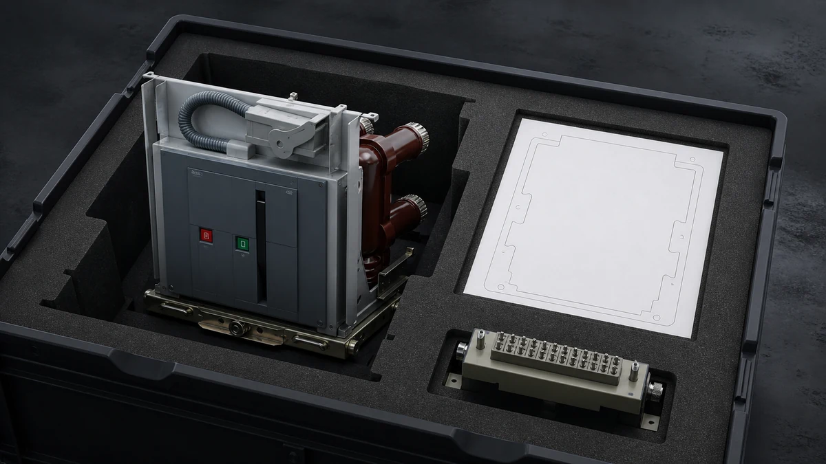
Send the request type, manufacturer, equipment model/year, part reference, ratings, quantity, destination, required date, and any drawing or photo notes. The SUVELL team will review the request.
Email: admin@suvell.com
Phone: +86 189 6871 1705
Factory: No.208 Wei 12 Rd, Yueqing Economic Development Zone, Wenzhou, Zhejiang, China
VS1 Vacuum Circuit Breaker Replacement: Nameplate and Interface Checklist
A matching VS1 nameplate does not establish full replacement compatibility. This checklist brings together breaker ratings, cubicle geometry, racking and earthing interfaces, interlocks, and auxiliary wiring so suppliers can compare a proposed unit against the actual fixed or withdrawable installation.
A VS1 replacement review needs the breaker nameplate, fixed or withdrawable construction, and the identity of the installed switchgear cubicle.
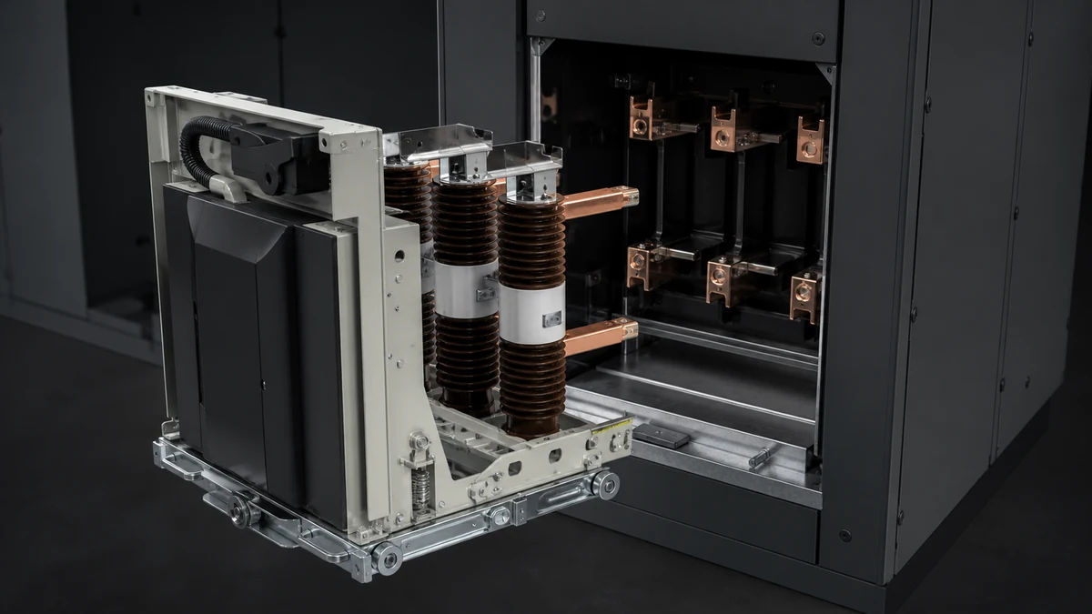
For drawout units, compare primary contacts, pole spacing, truck travel, earthing engagement, shutters, and door interlocks as one installed interface.
Record secondary plug pin assignments, control wiring, and motor and coil markings so a physically compatible breaker also matches the control system.
A **VS1 vacuum circuit breaker replacement** should not be approved from the rating plate alone. The nameplate confirms circuit-breaker-specific electrical identity, but replacement fit also depends on the installed switchgear, mechanical format, primary connection geometry, racking arrangement, earthing path, auxiliary wiring, interlocks, shutters, and door interface.
Use this checklist to collect replacement data before asking a supplier to confirm interchangeability. Record what is physically installed; do not rely on catalogue assumptions, panel labels, or a model code without photo evidence.
Replacement decision rule
Before selecting a replacement unit, confirm three data groups together:
**Nameplate data:** the electrical ratings and identifying information printed on the breaker.
**Breaker construction data:** fixed or withdrawable version, mechanism arrangement, accessories, and interlocks.
**Switchgear interface data:** the panel, cradle, racking, shutters, primary terminals, earthing, and auxiliary plug/socket arrangement.
If any one group is missing, the replacement assessment is incomplete.
Nameplate data to photograph and transcribe
Take a clear, straight-on photo of the breaker rating plate and transcribe every line exactly as printed. Do not normalize units, abbreviate manufacturer wording, or “correct” old markings.
Checklist item
Record / attach
Manufacturer name
Photo and typed text
Breaker type / model designation
Exact marking
Serial number or production number
Exact marking
Rated voltage
Exact marking
Rated current
Exact marking
Rated frequency
Exact marking, if shown
Short-circuit breaking rating
Exact marking
Short-time withstand / making information
Exact marking, if shown
Operating sequence or duty information
Exact marking, if shown
Control supply data printed on the plate
Exact marking, if shown
Standard or certification markings
Exact marking, if shown
Year of manufacture
Exact marking, if shown
The nameplate is the starting point, not the final compatibility proof. Manuals and catalogues for comparable medium-voltage vacuum circuit breakers distinguish ratings from dimensional variants, pole-spacing variants, mechanisms, auxiliary equipment, and interlocks; the same separation should be respected during a VS1 replacement review.
Breaker version and installation form
Confirm whether the installed breaker is a fixed unit or a withdrawable / drawout unit. This is a critical replacement boundary because a drawout breaker must match the original switchgear compartment as well as the electrical rating.
Record:
Fixed or withdrawable construction.
Indoor switchgear application details.
Panel or cubicle designation where the breaker is installed.
Switchgear manufacturer, switchgear type, and panel serial number if available.
Whether the breaker is installed in an original matched cubicle or a retrofit / modified panel.
Service position, test position, and disconnected position indications if withdrawable.
Any visible adaptor plates, special brackets, modified handles, or non-standard interfaces.
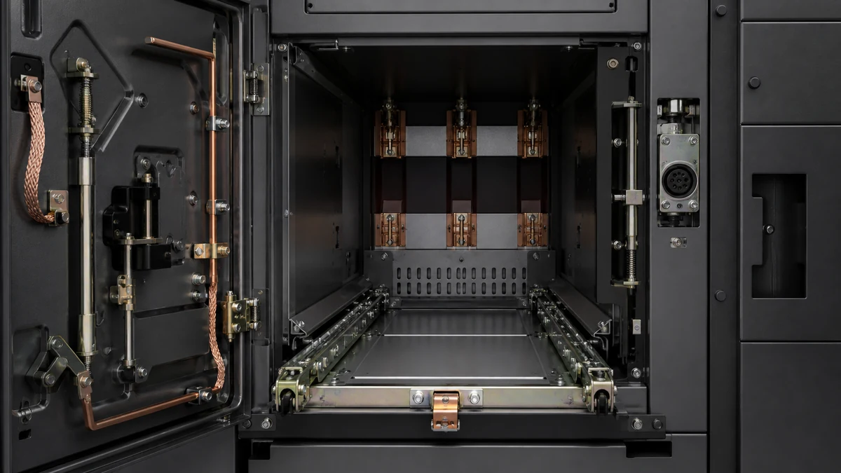
For a withdrawable breaker, include photos of the breaker outside the cubicle and photos of the empty compartment. A replacement unit must be matched to the installed switchgear context, not only to the breaker nameplate.
Primary medium-voltage interface checklist
The primary interface determines whether the replacement can physically engage the switchgear and maintain the intended electrical connection. Record the interface geometry rather than assuming it from the model name.
Do not approve a replacement based only on equal voltage and current ratings. Catalogue data commonly presents ratings alongside dimensional and pole-spacing variants, which means electrical rating and form factor must be checked together.
Mechanical fixation and truck interface checklist
For fixed units, verify the mounting base, bolt pattern, support frame, and terminal alignment. For withdrawable units, verify the truck, rails, wheels, guide pins, locking points, and racking drive.
Record:
Overall breaker dimensions as installed.
Height, width, and depth reference measurements.
Mounting hole pattern or truck frame geometry.
Wheel diameter, wheel spacing, and rail engagement, if withdrawable.
Guide rail profile and travel path.
Stop points and locking points.
Racking handle interface and direction of operation.
Mechanical position indicator location and wording.
Any compartment-side guides, catches, ramps, or stops.
Evidence of past mechanical modification.
A supplier should be able to compare the replacement breaker against the actual fixation and motion path. If the breaker cannot rack correctly, latch correctly, or align with the primary contacts, matching nameplate ratings will not solve the problem.
Earthing interface checklist
The earthing path is part of the installed interface. Capture both breaker-side and cubicle-side earthing features.
Check and document:
Breaker earthing contact or sliding earth contact location.
Cubicle earth contact location.
Contact engagement path during racking.
Visible condition of earthing surfaces.
Earth braid, contact block, or sliding shoe arrangement if present.
Continuity-related inspection notes from site maintenance records, if available.
Any labels or warnings connected with earthing sequence.
Do not assume that a replacement withdrawable unit will earth correctly unless the mechanical earth contact location and engagement sequence are verified.
Operating mechanism and stored-energy details
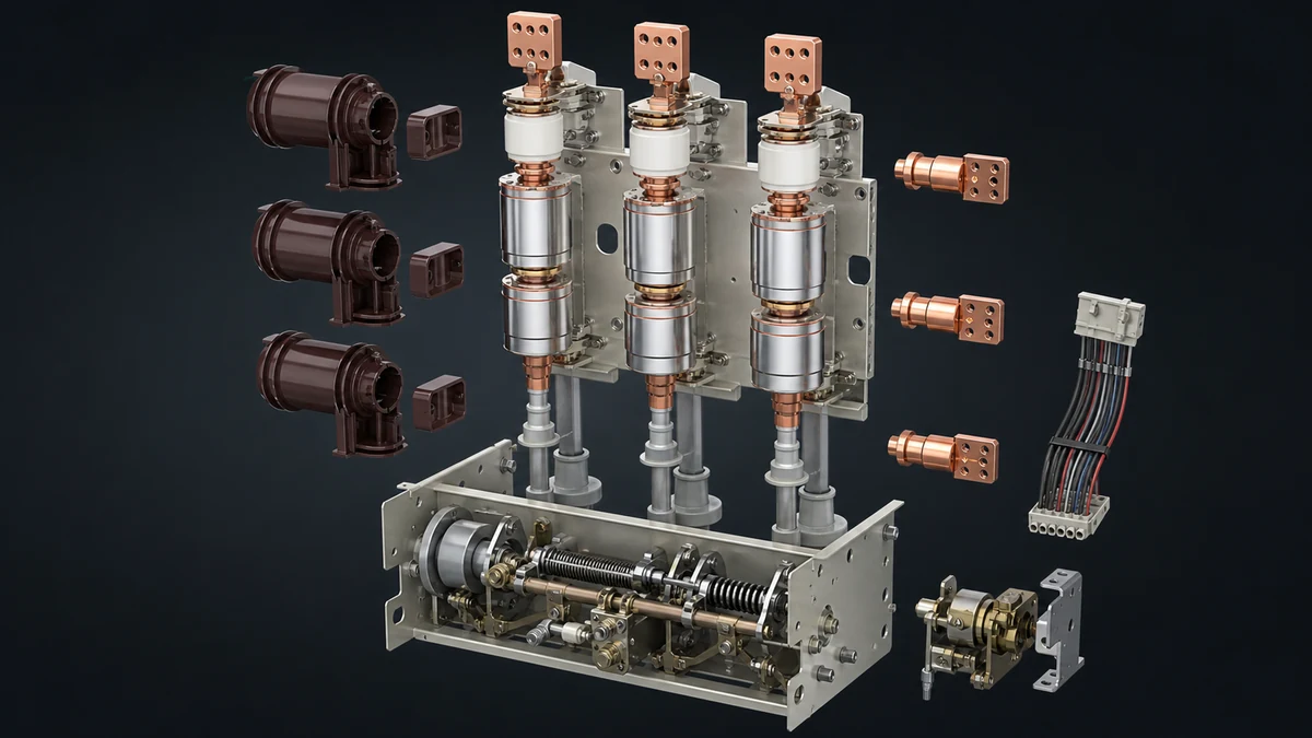
The operating mechanism is a separate compatibility area from the nameplate. Document the mechanism layout so the supplier can check charging, closing, opening, indication, and manual operation interfaces.
Record:
Manual or motor-charged spring mechanism arrangement.
Motor data as marked on the mechanism or accessory label.
Closing coil data as marked.
Opening / trip coil data as marked.
Undervoltage release data, if installed.
Shunt release or additional release devices, if installed.
Mechanical ON/OFF indicator style and location.
Spring charged / discharged indicator style and location.
Manual charging handle interface.
Manual close and manual trip button locations.
Operation counter location and reading.
Anti-pumping relay or device, if installed and identifiable.
Any customer-specific wiring or added components.
Do not replace the breaker solely by matching the main circuit rating if the mechanism accessories or control voltages differ.
Auxiliary wiring and secondary plug checklist
Auxiliary wiring is one of the most common reasons a physically similar breaker fails to function as a replacement. Photograph the secondary plug, socket, terminal blocks, wiring labels, and schematic references before disconnecting anything.
Data point
Required evidence
Secondary plug type
Clear photo of plug face and side
Pin count / terminal count
Count and photo
Pin numbering or terminal marking
Close-up photo
Cable entry direction
Photo
Harness routing
Photo before removal
Auxiliary contact arrangement
Wiring diagram or terminal list
Close circuit wiring
Schematic and terminal markings
Trip circuit wiring
Schematic and terminal markings
Motor charging circuit
Schematic and terminal markings
Position indication wiring
Schematic and terminal markings
Interlock circuit wiring
Schematic and terminal markings
Spare contacts in use
Confirm from actual wiring
If drawings are available, attach the control schematic and mark whether it matches the installed wiring. If drawings are not available, collect enough photos for a terminal-by-terminal comparison.
Interlock, shutter, and door interface checklist
Replacement assessment must include interlocks because the breaker is part of a switchgear safety system. Integration guidance for medium-voltage breakers commonly separates racking, shutters, door interlocking, mechanical fixation, earthing, primary interfaces, and auxiliary wiring; capture each group before proposing a replacement.
Document:
Door interlock type and engagement point.
Racking interlock position and operation.
Test / service / disconnected position interlocks.
Shutter operating arms or cams on the breaker.
Shutter engagement points inside the cubicle.
Earthing switch interlock relationship, if applicable.
Key interlocks, padlock provisions, or captive key systems.
Mechanical blocking devices.
Close/trip blocking conditions.
Any microswitches operated by breaker position.
Any interlock labels or warning plates.
A replacement breaker should not bypass, defeat, or leave unused an interlock that was active on the original installation.
Dimensional reference measurements
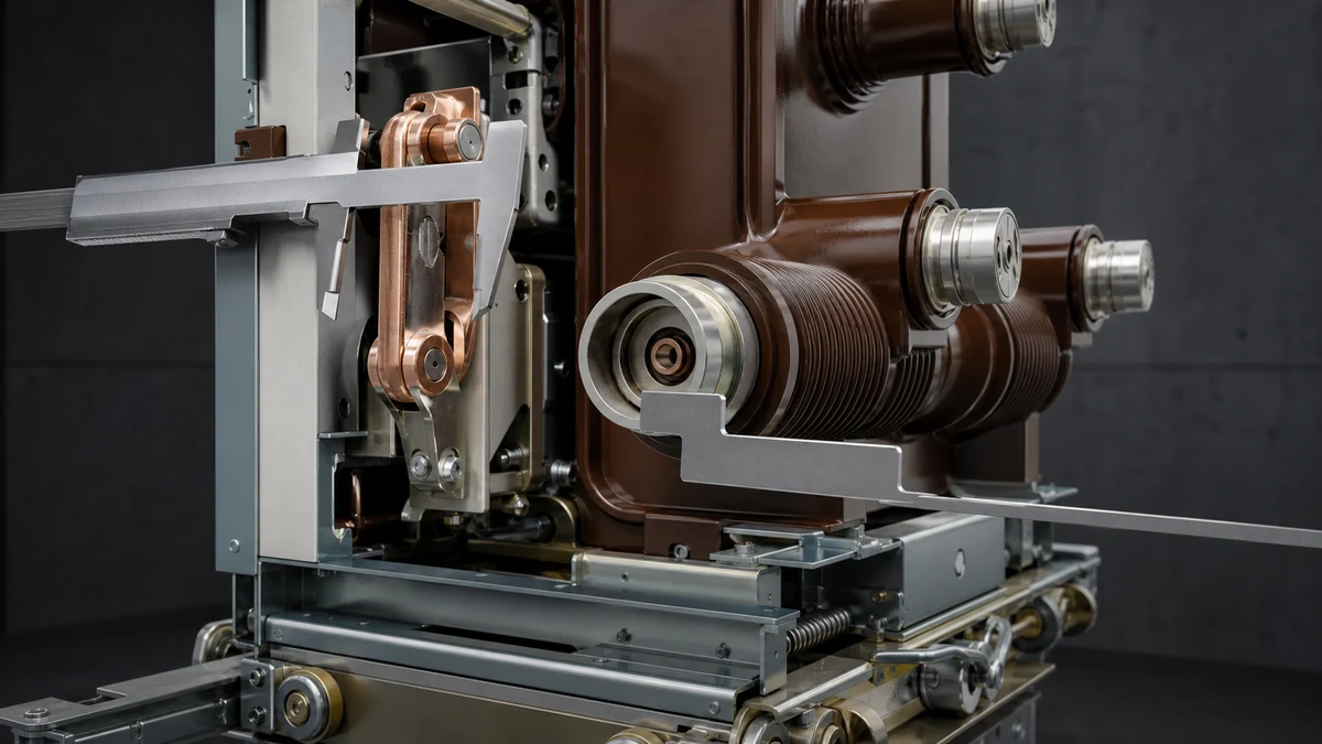
Take measurements only when the equipment is isolated, safe, and accessible under site procedures. Use photos with a ruler or measuring tape in frame wherever possible.
Record:
Overall breaker width, height, and depth.
Distance from front panel reference to primary contact centerline.
Distance from truck wheel centerline to primary contact centerline.
Pole-to-pole spacing.
Upper-to-lower terminal spacing.
Secondary plug location from fixed reference points.
Earthing contact location from fixed reference points.
Racking shaft location and profile.
Door cutout / escutcheon alignment if the breaker front interfaces with the door.
Handle insertion point location.
For decision-stage evaluation, approximate verbal descriptions are not enough. A supplier needs measurable interface data or clear reference photos.
Photo package checklist
Provide a complete photo set, not only the nameplate. Use consistent file names so each image can be traced to the installed breaker and panel.
Recommended photo set:
1. Breaker nameplate.
2. Full front view of breaker.
3. Full rear view of breaker.
4. Left and right side views.
5. Top and bottom views where accessible.
6. Primary contact close-ups.
7. Secondary plug and wiring close-ups.
8. Mechanism label and accessory labels.
9. Mechanism front with indicators visible.
10. Truck, wheels, guides, and racking parts.
11. Earthing contact on breaker.
12. Empty cubicle front view.
13. Cubicle primary contact area.
14. Cubicle shutter mechanism.
15. Cubicle secondary socket.
16. Cubicle rails and racking interface.
17. Door interlock and panel interlock parts.
18. Switchgear panel nameplate.
19. Wiring diagram or schematic photo.
20. Any damaged, modified, or non-standard parts.
Document package for supplier review
Send the supplier one consolidated package. A complete package reduces back-and-forth and prevents a replacement offer based on incomplete assumptions.
Include:
Nameplate photo and transcription.
Breaker installation form: fixed or withdrawable.
Switchgear manufacturer, type, and cubicle identification.
Control schematic and terminal list, if available.
Primary interface photos and measurements.
Secondary plug photos and pin / terminal data.
Mechanism accessory data.
Interlock and shutter interface photos.
Earthing interface photos.
Racking and truck interface photos for withdrawable units.
Dimensional sketch with key reference measurements.
Quantity required and whether units must be identical to each other.
Site constraints such as required outage window, but without substituting timing for technical confirmation.
Before issuing a purchase order, confirm that the replacement proposal addresses every item below.
The proposed breaker ratings match the required nameplate and system requirements.
The construction version matches the installation requirement.
The supplier has reviewed the installed switchgear context.
Primary contact geometry and pole spacing have been checked.
Mechanical fixation or truck/racking interface has been checked.
Earthing interface has been checked.
Secondary plug and auxiliary wiring have been checked.
Operating mechanism accessories and control supply markings have been checked.
Interlocks, shutters, and door interfaces have been checked.
Any deviations are listed in writing.
Any required adaptor, modification, or site work is clearly identified.
The replacement does not rely on unverified assumptions from model name alone.
Standards checklist
Standard / control
Status
Evidence reference
Nameplate data captured exactly as marked
Verified
Clear nameplate photo
Breaker form confirmed as fixed or withdrawable
Verified
Contact and truck interface photos
Primary interface measured and photographed
Verified
Contact and truck interface photos
Mechanical fixation or truck interface documented
Verified
Contact and truck interface photos
Earthing interface documented
Verified
Site photos / maintenance record
Operating mechanism and accessories documented
Verified
Mechanism label photos
Auxiliary wiring and secondary plug documented
Verified
Plug and wiring photos
Interlocks, shutters, and door interface documented
Verified
Cubicle and door-interface photos
Supplier compatibility review completed
Pending / Verified
Supplier submission
Approval record filed with equipment history
Pending / Verified
Commissioning / handover file
FAQ
What is the minimum data needed for a VS1 vacuum circuit breaker replacement?
The minimum data package should include the breaker nameplate, fixed or withdrawable version, switchgear panel identification, primary contact photos, secondary plug details, operating mechanism accessory data, racking or mounting details, earthing interface, and interlock / shutter information. A nameplate photo alone is not enough to establish full compatibility.
What is missing if only the breaker nameplate is provided?
The missing items are the mechanical and control-circuit interfaces. The nameplate identifies circuit-breaker-specific rating information, but it does not prove that the replacement will match the cubicle, truck, primary contacts, auxiliary plug, racking system, shutters, earthing contact, or door interlock.
What is the most important check for a withdrawable VS1 replacement?
The most important check is the complete drawout interface: truck geometry, guide rails, racking mechanism, service and test positions, primary contact engagement, secondary plug engagement, earthing contact, shutter actuation, and interlocks. A withdrawable breaker must match the installed metal-clad switchgear compartment, not only the electrical rating.
What is the role of the switchgear panel nameplate?
The switchgear panel nameplate helps identify the cubicle context in which the breaker operates. Replacement matching depends on both the breaker and the panel because the breaker interfaces with panel-mounted primary contacts, shutters, rails, earthing parts, interlocks, wiring sockets, and door mechanisms.
What is the safest way to handle uncertain replacement data?
Treat uncertain data as open until verified by photos, measurements, drawings, or site inspection. Do not approve a replacement based on assumed interchangeability. If the installed breaker or cubicle has been modified, highlight the modification and ask the supplier to confirm whether the proposed replacement remains mechanically and electrically compatible.
LEO Chen
With more than 20 years of industry experience, LEO Chen has worked with major companies on switchgear, transformer components and medium-voltage equipment projects. He contributes practical guidance for engineers and sourcing teams, with a focus on clear selection criteria, application context and the information needed to prepare an informed RFQ. Connect with LEO on LinkedIn.