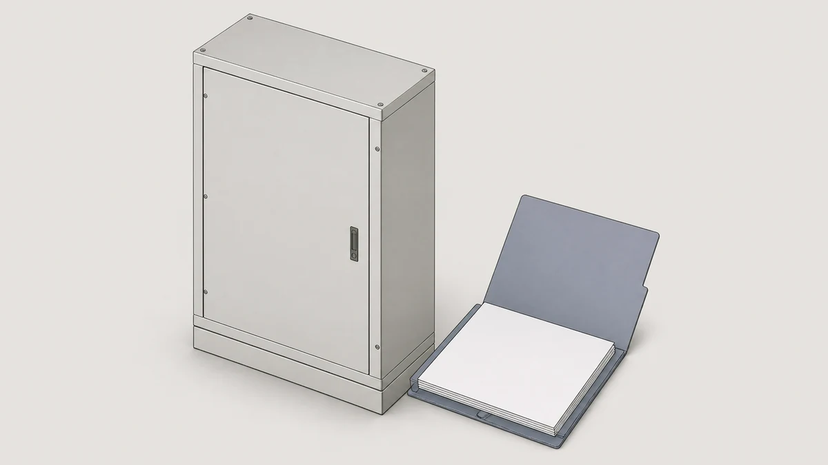
Send the request type, manufacturer, equipment model/year, part reference, ratings, quantity, destination, required date, and any drawing or photo notes. The SUVELL team will review the request.
Email: admin@suvell.com
Phone: +86 189 6871 1705
Factory: No.208 Wei 12 Rd, Yueqing Economic Development Zone, Wenzhou, Zhejiang, China
A VS1 replacement must work with the compartment's racking, shutters, secondary connections, and interlocks. This guide identifies the drawings and interface comparisons needed to assess fit, explains why a shared breaker designation is insufficient, and highlights mismatches that may remain hidden during simple insertion.
Compare racking rails, drive engagement, stop positions, and shutter actuator geometry between the proposed VS1 breaker and its target compartment.
Match secondary plug coding and pin assignments to the panel wiring, and verify interlock actuation and rating-code features.
Resolve missing compartment and breaker drawings with the relevant manufacturers before procurement or a physical fit trial.
A VS1 vacuum circuit breaker's nameplate ratings tell you nothing about whether it will physically and electrically integrate with an existing compartment. Compatibility turns on four distinct interface systems — the racking mechanism, the shutter assembly, the secondary disconnect plug, and the interlocks — each of which can be configured differently even within the same switchgear family. Before any racking or replacement decision, the compartment drawing and breaker outline drawing must be compared directly; the breaker family name alone does not authorize a drop-in substitution.
—
Why Compartment Compatibility Is a Distinct Engineering Question
The VS1 is a withdrawable vacuum circuit breaker, meaning it moves between at least three positions — service (connected), test (control circuits live, primary isolated), and isolated (fully withdrawn) — along a set of guides inside the compartment. Each position transition involves mechanical engagement of different interface systems simultaneously. A mismatch in any single interface can prevent racking, defeat an interlock, leave shutters inoperable, or strand the control circuit mid-operation.
This is not a quality or vendor-preference question. It is a dimensional and kinematic one. The compartment was built to accept a specific breaker geometry and interface sequence. The ABB medium-voltage switchgear instruction manual addresses this directly when it explains that control-wiring plug connections can be coded to assign withdrawable switching devices to particular panels — a design feature that exists precisely because physical fitment between compartment and breaker cannot be assumed from the breaker family name alone.
Two compartments built to different generations of the same switchgear platform will frequently share a breaker model designation but differ in racking-rail spacing, shutter-actuator geometry, secondary-plug face coding, or interlock-cam profile. The consequence of overlooking this is not just a failed installation — it can be a defeated interlock that allows racking into a live bus, or a control circuit that connects partially and energizes a coil at the wrong time.
—
The Racking Mechanism: Dimensional and Force Interface
The racking mechanism translates rotational input from a racking handle into linear travel of the breaker carriage along the compartment guides. Compatibility depends on three independent dimensions: the guide-rail profile (width, height, and engagement depth), the racking-screw or racking-cam geometry at the drive point, and the travel distance between each defined position.
Rail profile mismatches are the most immediately obvious failure mode — the breaker either will not enter the compartment or will rock laterally, preventing smooth travel. Less obvious is a racking-screw pitch mismatch: a breaker may enter the compartment and begin racking but bind or strip at the drive engagement point if the thread pitch or drive geometry does not match the compartment's lead screw. Still less obvious is a travel-distance mismatch, where the breaker reaches mechanical stops before reaching the intended service or test position, leaving the primary contacts partially engaged or the secondary plug not fully seated.
The practical verification step is to obtain both the compartment outline drawing (typically issued with the switchgear panel) and the breaker insertion drawing for the VS1 variant being considered. These will show guide-rail cross-sections, racking-drive engagement dimensions, and stop positions. Compare them before any physical trial; attempting to force a mismatched breaker through the racking sequence can damage shutters, bend guides, or trip interlocks in ways that require compartment-level repair.
—
Shutter Assembly: Function, Actuation Geometry, and Interlock Relationship
Shutters cover the primary circuit bus stabs when the breaker is withdrawn. Their function is personnel protection: they prevent inadvertent contact with live busbars during breaker removal, insertion, or inspection. In most medium-voltage compartment designs, the shutters are mechanically actuated by the breaker carriage itself — a cam or pin on the carriage engages the shutter mechanism as the breaker travels toward the service position and retracts the shutters in a controlled sequence.
The Schneider Electric SureSeT user guide identifies shutter interlocks as a distinct compartment feature, separate from the racking mechanism. This matters because the shutter actuator geometry is matched to the breaker's carriage profile. A replacement breaker with a different carriage height, a shifted actuator pin, or a different cam profile may fail to open the shutters fully (preventing connection to the bus stabs), open them prematurely (exposing live stabs before the breaker is properly positioned), or fail to close them on withdrawal.
Shutter interlocks add another layer. Many compartments include a shutter-locking feature that physically prevents the shutters from opening unless the breaker carriage is correctly positioned and a defined mechanical condition is met. The ABB manual describes shutter locking as a distinct panel function. A breaker that does not actuate this interlock correctly will either be locked out of the service position or, more dangerously, will enter the service position without confirming proper shutter state.
The verification question is whether the replacement breaker's carriage actuates the shutter mechanism through the same geometry as the original. This requires comparing the shutter-actuation interface dimensions from both the compartment drawing and the breaker insertion drawing side by side.
—
Secondary Disconnect Plug: Coding, Pin Layout, and Mating Force
The secondary disconnect plug carries control wiring — trip and close coil circuits, auxiliary contacts, protection relay signals, motor-charged spring feedback, and any other low-voltage signals between the compartment and the breaker. It mates automatically as the breaker approaches or reaches the test position, before the primary contacts engage.
The ABB manual describes coding of the control-wiring plug connection explicitly, noting that coding allows withdrawable switching devices to be assigned to particular panels. Coding is implemented through physical keys, asymmetric pin arrangements, or polarizing features on the plug face that prevent a breaker with a different control-interface assignment from seating in the wrong panel. This is an intentional compatibility barrier, not a tolerance issue — it is designed to prevent a breaker with, for example, a different auxiliary-contact assignment from being installed in a panel where the wiring expects a different signal mapping.
For replacement decisions, this means that even a dimensionally compatible VS1 variant may be coded differently from the original. The replacement must be ordered or configured to match the compartment's plug receptacle coding, pin count, and pin assignment map. Ordering by breaker catalog number alone is insufficient; the secondary interface specification must be drawn from the panel documentation.
Mating force is a separate consideration. Medium-voltage secondary plugs are rated for a defined number of mating cycles, and the spring-loaded contact pins degrade with repeated cycling. A plug that requires excessive force to seat suggests misalignment or pin damage, not a tight tolerance fit — forcing it can bend pins and corrupt the control circuit.
—
Interlock Systems: Panel-Level Logic and Position Confirmation
Interlocks in a withdrawable circuit breaker compartment serve two distinct purposes that are often conflated: position confirmation (the switchgear control system knows where the breaker is) and operation prevention (the breaker or compartment cannot be moved when doing so would create a hazard). Both depend on correct mechanical engagement between the breaker and the compartment.
Position-confirmation interlocks typically use auxiliary switches or proximity sensors triggered by the breaker carriage at defined travel points. The compartment is wired to expect actuation at specific positions — if the replacement breaker's actuating geometry differs, the position logic will misread the breaker's location. Depending on the protection relay's logic, this can prevent closing, prevent opening, or generate a spurious alarm.
Prevention interlocks include mechanisms that block racking with the breaker closed (to prevent withdrawing a closed breaker under load), block closing in the test position in certain configurations, and in some designs block racking unless an earthing switch is in a defined state. The ABB manual describes panel interlocks in this prevention role. These interlocks depend on the breaker presenting specific mechanical features at defined positions — a cam profile that actuates a lever, a pin that engages a blocking slot, or a surface that compresses a switch actuator. A replacement breaker must replicate these features at the same positions with the same geometry, or the interlock will either fail to engage (undetected hazard) or engage spuriously (operational lockout).
The Schneider SureSeT documentation identifies rating-code protection as a separate compartment feature alongside interlocks and racking. Rating-code protection uses physical barriers or keying to prevent installation of a breaker with an incompatible current or voltage rating in a given panel position. This is worth noting because a breaker that passes dimensional checks may still be blocked by rating-code protection if the replacement has a different frame size or rating code than the original.
—
Interface Review Workflow Before Replacement or RFQ
The four interface systems interact, so the review is most efficient when treated as a parallel check against a single set of documents rather than a sequential checklist. The documents needed are:
The compartment outline or arrangement drawing, including the racking-mechanism detail
The secondary disconnect receptacle wiring diagram and plug-face layout, with coding details
The original breaker's insertion drawing, showing carriage dimensions and actuator geometry
The replacement VS1's insertion drawing, for the same fields
With those in hand, the verification questions are:
1. Do the guide-rail profiles and racking-drive engagement dimensions match between compartment drawing and replacement breaker drawing?
2. Does the replacement carriage actuate the shutter mechanism through the same geometry and at the same travel points?
3. Does the secondary plug on the replacement match the compartment receptacle in coding, pin count, and pin assignment?
4. Does the replacement breaker present the interlock-actuation features (cams, pins, surfaces) at the same positions as the original, with the same geometry?
5. Does the replacement's rating code match the compartment's rating-code protection barriers?
If any question cannot be answered from available drawings, the gap must be resolved with the OEM or the switchgear manufacturer before physical trial. A physical trial with an unverified replacement is not a documentation substitute — it can produce a misleading partial pass that fails in service.
—
Installation Risks from Undocumented Substitution
The failure modes from an incompatible installation are not all immediately visible. A breaker that racks in and out without obvious resistance may still have defeated an interlock, misseated the secondary plug, or opened the shutters through a geometry that will crack the actuator after several operations.
Partial secondary plug seating is a particularly insidious risk. If the plug seats far enough to make some pin contacts but not others, the breaker may close and open on command while failing to report auxiliary contact state correctly or while leaving a coil circuit floating. Protection relay misoperation, spurious tripping, or failure to trip can follow.
Shutter actuator wear from geometric mismatch is gradual. The shutter mechanism is designed for a specific contact geometry and force profile. A replacement with a shifted actuator pin will impose off-axis force on the shutter linkage every cycle, accelerating wear on plastic or light-alloy components that are not designed for that load path. The failure often appears as a shutter that opens slowly or incompletely, well after the installation is complete and the substitution connection is forgotten.
Interlock defeat is the highest-consequence failure mode. If the replacement breaker does not engage a prevention interlock correctly, the mechanical block is absent. Operators relying on the interlock to confirm safe racking conditions will be working without the protection the system was designed to provide.
—
Data Required for a VS1 Replacement RFQ
A complete RFQ for a VS1 in an existing compartment requires more than a breaker catalog number. The minimum data set for the compartment interface is:
Switchgear panel type and serial number, from which the OEM can confirm the applicable compartment drawing revision
Breaker carriage outline drawing number, from the original installation records or the panel documentation package
Secondary plug type code and wiring diagram number, including pin count, coding key, and signal assignment
Racking mechanism type and drive engagement specification
Interlock system description, including which interlocks are present and which mechanical features on the breaker actuate them
Rating-code barrier configuration, to confirm the replacement will pass rating-code protection without modification
Where panel documentation is incomplete, the OEM of the switchgear (not only the breaker manufacturer) is the authoritative source. The breaker manufacturer can confirm what the VS1 presents at each interface; the switchgear OEM can confirm what the compartment expects. Both perspectives are needed, and a discrepancy between them must be resolved before procurement.
—
FAQ
What is VS1 breaker compartment compatibility?
VS1 breaker compartment compatibility refers to whether a VS1 vacuum circuit breaker will correctly engage all four mechanical and electrical interface systems of a specific withdrawable compartment: the racking mechanism, the shutter assembly, the secondary disconnect plug, and the interlock system. Because each of these interfaces can be configured differently across switchgear generations and manufacturers, compatibility must be verified from drawings rather than assumed from the breaker's catalog designation.
What is the purpose of secondary plug coding in a VS1 compartment?
Secondary plug coding uses physical keys, asymmetric pin arrangements, or polarizing features to prevent a breaker with a different control-circuit assignment from seating in the wrong panel position. As documented in ABB medium-voltage switchgear instructions, coding allows withdrawable switching devices to be assigned to particular panels. A replacement VS1 must match the compartment's plug coding exactly, or it will not seat in the receptacle regardless of its primary-circuit ratings.
What is the risk of a shutter actuator geometry mismatch?
If a replacement breaker's carriage presents the shutter actuator at a different position or with a different geometry than the original, the shutters may not open fully at the service position (preventing primary contact engagement), may open prematurely during racking (exposing live busbars), or may impose off-axis force on the shutter linkage that accelerates mechanical wear. Shutter interlocks, identified in Schneider SureSeT documentation as a distinct compartment feature, may also fail to confirm correct shutter state, generating false position signals.
What is rating-code protection in a medium-voltage breaker compartment?
Rating-code protection is a physical keying or barrier system in the compartment that prevents installation of a breaker with an incompatible current or voltage rating. The Schneider SureSeT documentation identifies it as a separate compartment feature alongside racking mechanisms and shutter interlocks. A replacement VS1 with a different frame size or rating code may be physically blocked by rating-code barriers even if its external carriage dimensions otherwise appear compatible.
What is the minimum document set needed before replacing a VS1 in an existing panel?
The minimum set is: the compartment outline and racking-mechanism drawing, the secondary plug wiring diagram with pin assignments and coding details, the original breaker's insertion drawing, the replacement VS1's insertion drawing, the interlock system description, and the rating-code barrier configuration. Where any of these are missing, the switchgear OEM is the authoritative source; the breaker manufacturer alone cannot confirm compartment-side interface requirements.
LEO Chen
With more than 20 years of industry experience, LEO Chen has worked with major companies on switchgear, transformer components and medium-voltage equipment projects. He contributes practical guidance for engineers and sourcing teams, with a focus on clear selection criteria, application context and the information needed to prepare an informed RFQ. Connect with LEO on LinkedIn.