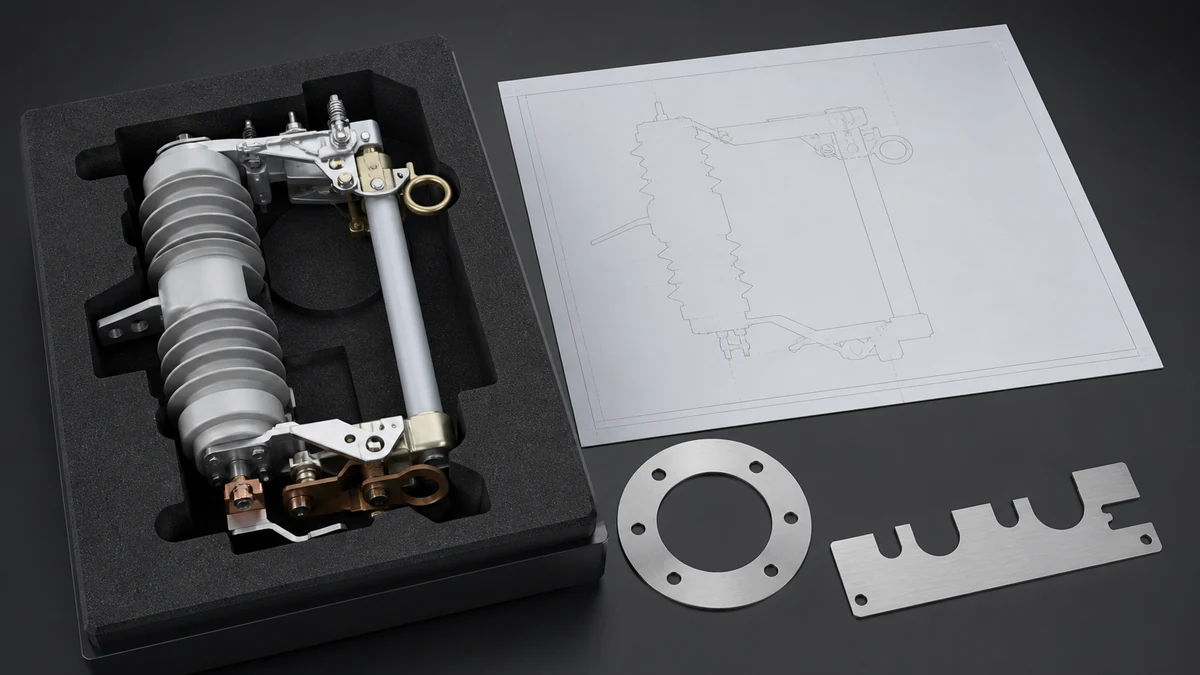
Send the request type, manufacturer, equipment model/year, part reference, ratings, quantity, destination, required date, and any drawing or photo notes. The SUVELL team will review the request.
Email: admin@suvell.com
Phone: +86 189 6871 1705
Factory: No.208 Wei 12 Rd, Yueqing Economic Development Zone, Wenzhou, Zhejiang, China
Transformer-Mounted Loadbreak Switch Replacement: Position and Interface Checklist
Transformer-mounted loadbreak switch replacement starts with the installed arrangement. This RFQ checklist separates switch identity, mounting position, primary connections, and access interlocks, helping buyers compare supplier drawings with site evidence and identify adaptations or unresolved interface questions before placing an order.
Identify the installed transformer’s loadbreak switch medium, mechanism type, position arrangement, and application from its markings and equipment records.
Document mounting orientation, anchors, openings, and access clearances separately from bus connections, conductor routes, and terminal interfaces.
Ask the supplier to address drawing discrepancies, required adaptations, and access-interlock compatibility explicitly before treating a quote as a confirmed replacement.
Standards Checklist
Requirement
Status
Evidence reference
Confirm switch identity, medium, mechanism, and application
Pending
Nameplate, supplier data, installation record
Verify position, orientation, and mounting relationship
Pending
Photos, drawing references
Match bus, conductor, and termination interface
Pending
Connection photos, terminal records
Review drawings and enclosure context together
Pending
Drawing set, enclosure records
Verify access interlocks before energization
Pending
Interlock test record
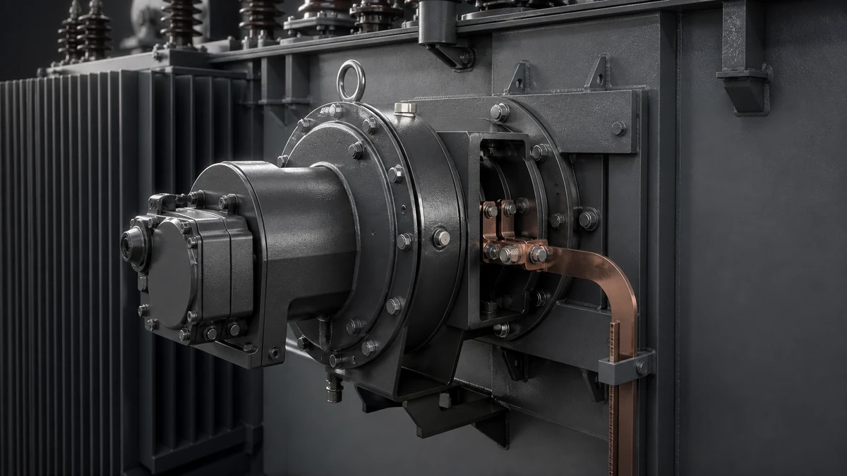
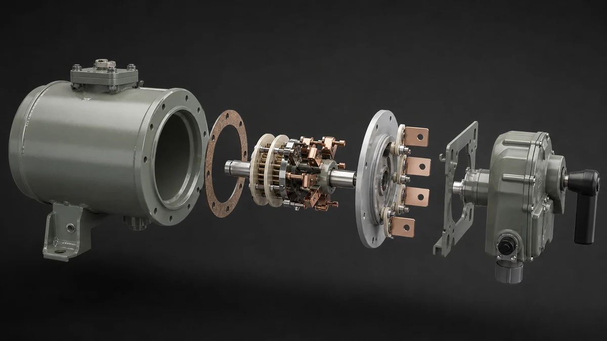
For **transformer loadbreak switch replacement**, the decision should start with the installed position and interface, not with appearance alone. The supplied evidence points to a manually operated, two-position, oil-immersed rotary load-make-or-break switch used on distribution transformers and self-contained distribution switchgear, so the replacement record should capture both mechanism type and application before selection is approved.
This article is for RFQ preparation and technical comparison only. It does not authorize switching, removal, installation or energization. Any replacement must be reviewed against the actual transformer or enclosure drawings and accepted through the applicable qualified engineering and site-safety process.
Keep one replacement record for each installed position
Create a separate record for every switch position rather than applying one photo set across several transformer units. The record should make it obvious which evidence describes the existing switch, its mounting location and the connection or access interfaces around it.
Record group
What to capture
Why it is separate
Identity and function
Markings, documented switch type, oil medium, mechanism form and application
Establishes the correct family without assuming a visible match
Position and mounting
Transformer or enclosure position, orientation, anchors, opening and clearances
Shows whether a candidate can be physically reviewed against the installation
Primary interface
Bus, conductor, terminal and adapter relationship
Prevents a rating-only comparison
Access and interlocking
Door, access hardware, key or mechanical interlock relationship
Keeps operating-safety functions visible in the RFQ
Evidence gaps
Unreadable markings, unavailable drawings or ambiguous photos
Tells the supplier what must be confirmed rather than guessed
1) Record the exact switch identity from the installed record
[ ] Confirm the switch medium is oil-immersed if that is what the source documentation shows.
[ ] Record whether the existing unit is manually operated.
[ ] Note whether the mechanism is a two-position rotary load-make-or-break type.
[ ] Capture the stated application: distribution transformer, self-contained distribution switchgear, or both as documented.
[ ] Do not approve a replacement from a single visible external feature alone.
2) Verify position, orientation, and mounting relationship
[ ] Identify the exact position of the switch within the transformer or enclosure.
[ ] Document how the unit is oriented in the installed arrangement.
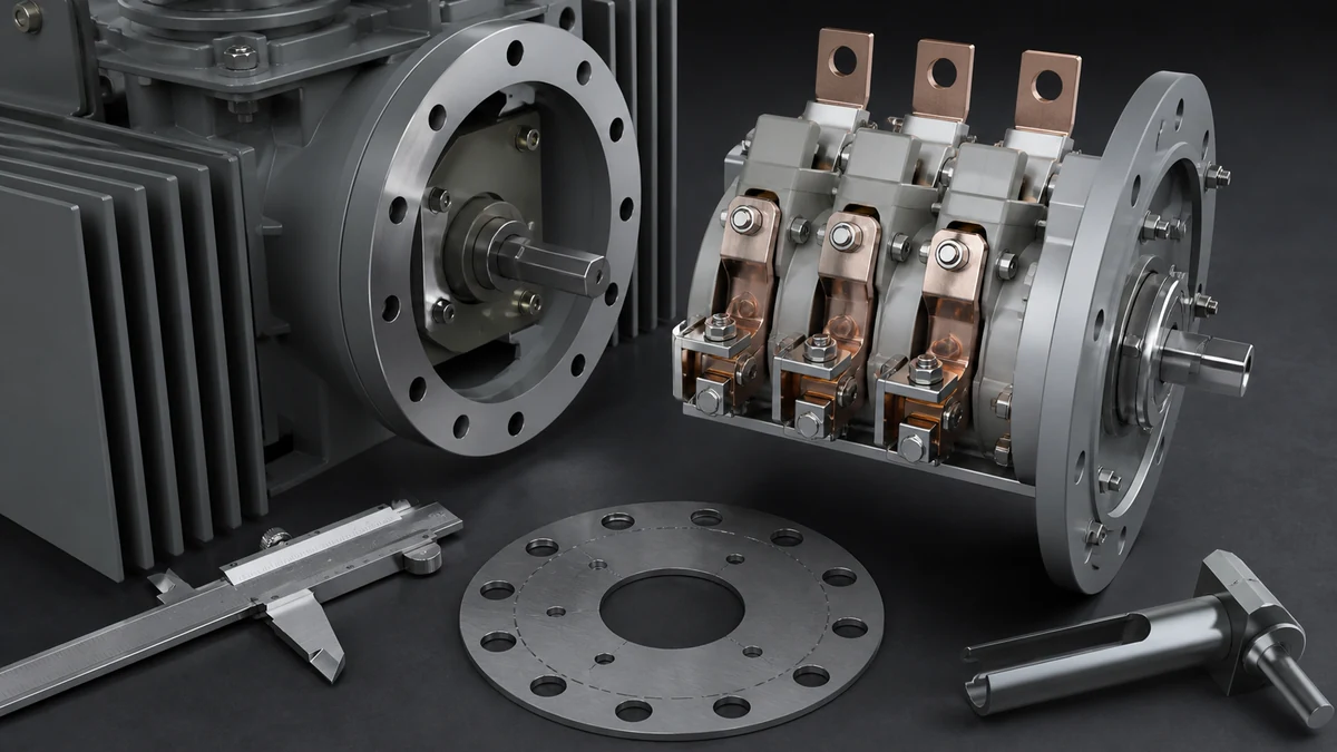
[ ] Record anchoring points and any hardware that holds the switch in place.
[ ] Note clearances, service access, and physical constraints that affect removal and installation.
[ ] Separate mounting evidence from electrical connection evidence in the replacement file.
[ ] Capture any enclosure context that changes how the switch sits in the assembly.
Photograph the position from a wide view before taking close-ups. A close-up can show a bracket or shaft, but it may not show whether the switch is part of a transformer tank, a self-contained enclosure, or an arrangement with restricted access. Retain one image that relates the switch to its surrounding interfaces.
3) Match the bus, conductor, and termination interface
[ ] Document bus connections as installed.
[ ] Record conductor entry points and termination details.
[ ] Note any adapters, interface parts, or spacing elements already in use.
[ ] Compare the installed transformer or enclosure interface with the supplier drawing set.
[ ] Keep connection evidence separate from interlock evidence.
Where a drawing is available, identify the drawing number and revision in the RFQ rather than copying estimated dimensions into a supplier request. Add a short field sketch only to identify the photographed reference points and any observed obstruction; it is not a substitute for the approved outline or arrangement drawing.
4) Review drawings and enclosure context together
[ ] Collect installation drawings that show the switch in the equipment configuration.
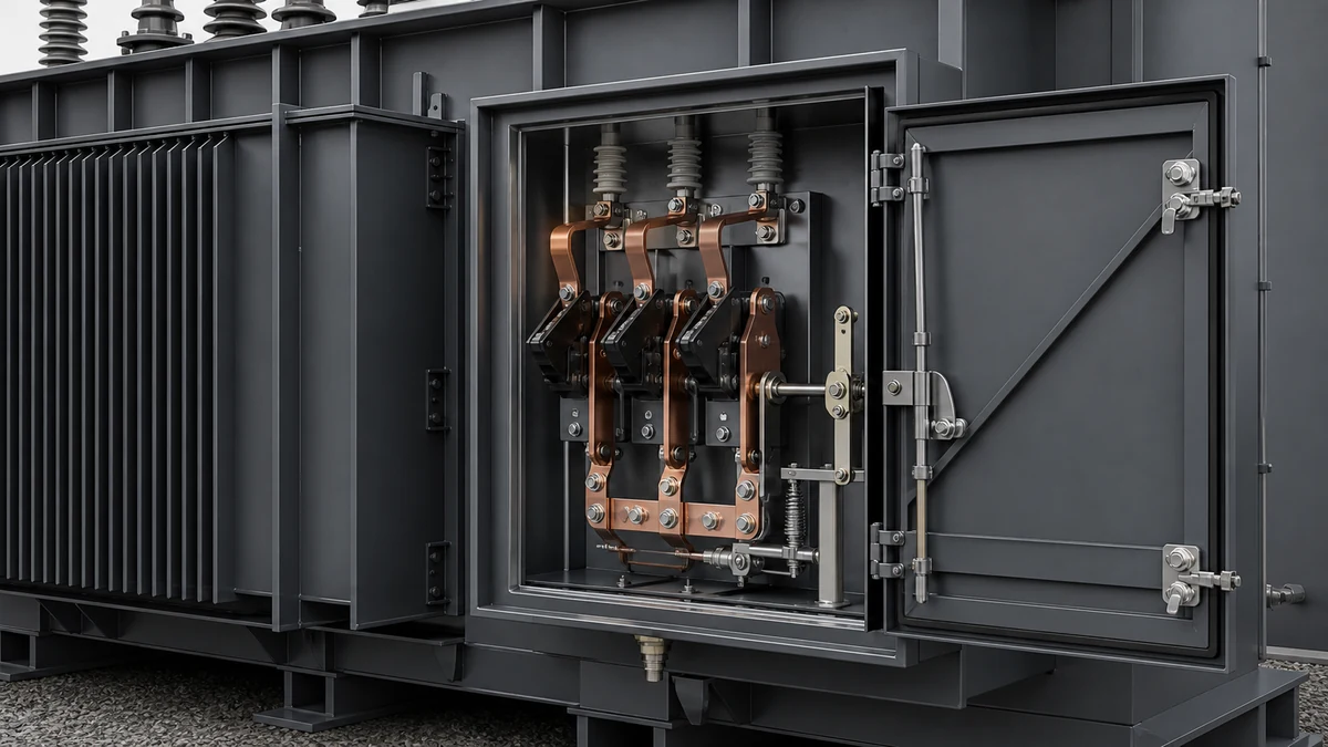
[ ] Confirm the enclosure or tank context in which the switch is installed.
[ ] Check whether the replacement must fit an existing opening, bracket, or access path.
[ ] Identify any drawing notes that affect removal, refit, or alignment.
[ ] Use the drawing set to confirm that the replacement matches the installed arrangement, not just the visible hardware.
[ ] Treat the transformer or enclosure interface as part of the replacement decision.
Compare the drawing and the installed condition
Before asking for a technically confirmed proposal, make a small discrepancy log. It stops a supplier from treating an old drawing or one exterior photograph as conclusive evidence.
Check
Drawing or record evidence
Installed evidence
Action if unresolved
Switch location and orientation
Arrangement drawing
Context photo
Request confirmation of the installed position
Mounting and opening
Outline or enclosure drawing
Anchor and clearance photos
Flag any visible mismatch for review
Bus and conductor route
Connection drawing
Termination photos
Keep the connection question open
Interlock relationship
Interlock drawing or documented sequence
Hardware and access photos
Require technical confirmation before release
The table is a control tool, not a field acceptance record. Its purpose is to surface the questions that a product drawing, supplier response or qualified site inspection must resolve.
5) Verify access interlocks before energization
[ ] Record the interlock condition as a pre-energization check.
[ ] Confirm that access interlocks function independently of the switch body and bus terminations.
[ ] Verify that the switch can be accessed and operated only in the intended condition described by the equipment arrangement.
[ ] Document any interlock hardware that must be retained, adjusted, or replaced.
[ ] Do not merge interlock checks with mounting or connection checks.
[ ] Recheck the access sequence after any replacement trial fit.
6) Build the replacement request packet
[ ] Existing switch identification record
[ ] Photos of the installed position
[ ] Photos of mounting and anchoring points
[ ] Photos of bus connections and conductor terminations
[ ] Drawing references for the transformer or enclosure interface
[ ] Interlock condition evidence
[ ] Notes on any mismatch risk that cannot be resolved from appearance alone
State the required supplier response
Ask the supplier to respond to each interface group separately. A useful response should state whether the proposed switch is a direct replacement, requires an adaptation, needs more evidence, or cannot be confirmed from the supplied record. It should also identify accessories, mounting changes, connection changes or site work that would be needed before any installation review.
Do not interpret a commercial quote as confirmation of every interface. If the supplier has not addressed an open item, leave it marked as an engineering risk and obtain the required drawing or inspection evidence before placing an order.
FAQ
What is the minimum evidence set for transformer loadbreak switch replacement?
The minimum set is the installed switch identity, application, mechanism type, oil medium, operating-current class, switch form, mounting position, and interface drawings. If any of those items are missing, the replacement decision is still incomplete.
What is the safest way to avoid matching by appearance alone?
Use documentation, not exterior appearance. The evidence supplied for this product family shows that no single visible feature is enough to establish a match, so the review must combine nameplate data, mounting evidence, connection details, and enclosure context.
What is the difference between mounting evidence and connection evidence?
Mounting evidence shows where the switch sits, how it is anchored, and how it fits the transformer or enclosure. Connection evidence shows how the bus or conductors terminate at the switch and whether the replacement preserves the same interface.
What is the most important pre-energization check?
Interlock condition is the key pre-energization check. The replacement file should confirm that access interlocks are documented and verified separately from the mounting and bus-connection review.
What is the best way to document the installed arrangement?
Capture the transformer or enclosure context together with drawings, photos, and interface notes. That gives the supplier enough information to compare the installed arrangement with the replacement candidate without guessing from the outside of the switch.
LEO Chen
With more than 20 years of industry experience, LEO Chen has worked with major companies on switchgear, transformer components and medium-voltage equipment projects. He contributes practical guidance for engineers and sourcing teams, with a focus on clear selection criteria, application context and the information needed to prepare an informed RFQ. Connect with LEO on LinkedIn.