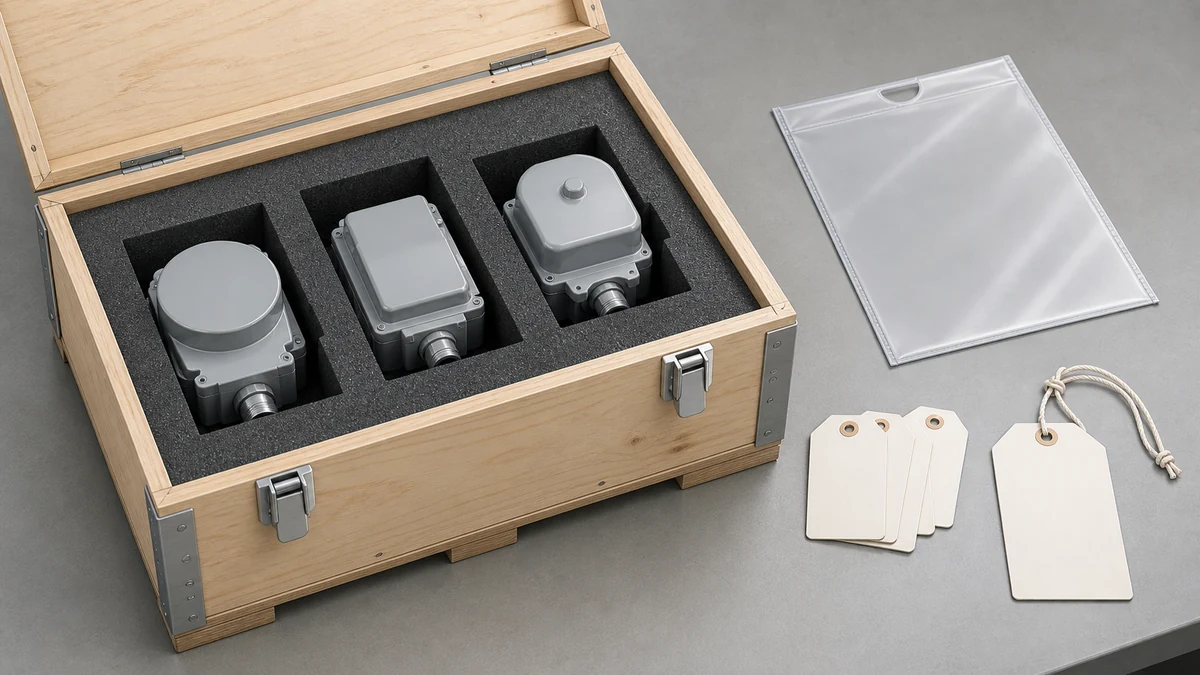
Send the request type, manufacturer, equipment model/year, part reference, ratings, quantity, destination, required date, and any drawing or photo notes. The SUVELL team will review the request.
Email: admin@suvell.com
Phone: +86 189 6871 1705
Factory: No.208 Wei 12 Rd, Yueqing Economic Development Zone, Wenzhou, Zhejiang, China
Transformer Gauge, Indicator, and Pressure-Relief Device: What Each One Tells You
Transformer pressure gauges, indicators, and relief devices provide different information and actions. This guide separates pressure display from mechanical relief and explains how optional flags, alarm contacts, scale ranges, and connection details affect specification, replacement compatibility, and integration with the wider monitoring system.
A pressure/vacuum gauge reports tank conditions, while a pressure-relief device vents excess pressure; their monitoring and mechanical functions are complementary.
Local operation flags, alarm switches, and remote outputs depend on the selected configuration and must be specified where the project requires them.
Match scale range, process connection, mounting, contact ratings, and signal interfaces, then map each accessory to the transformer’s monitoring and protection scheme.
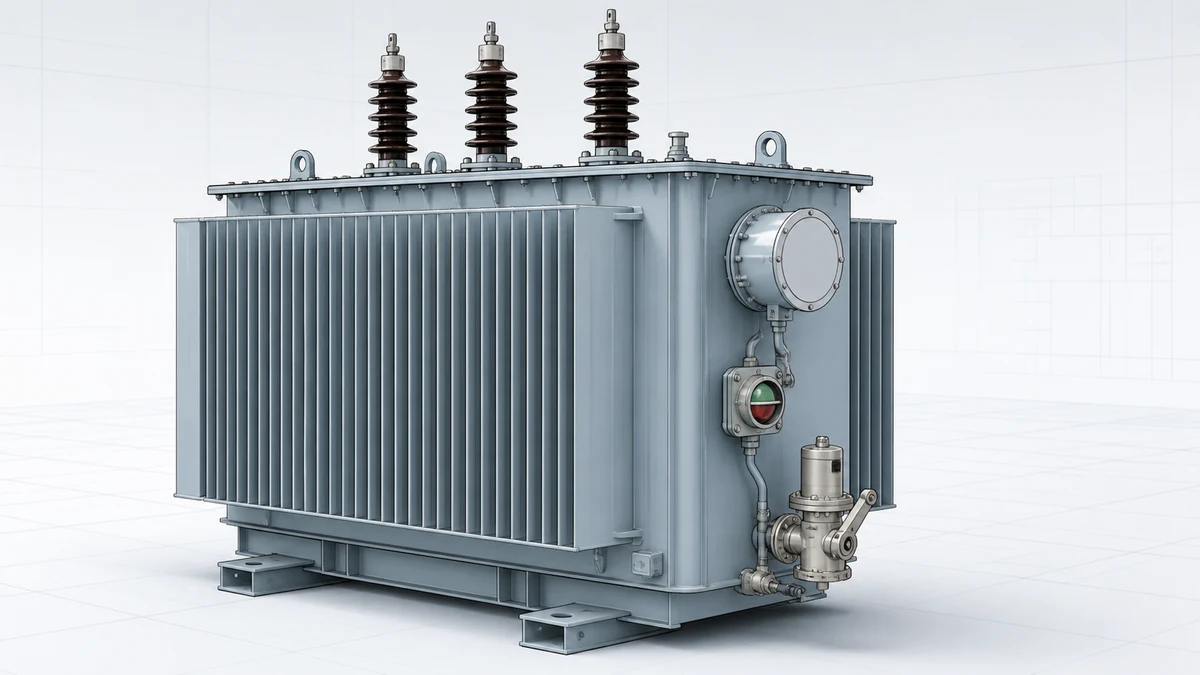
Transformer tank accessories divide into two functional classes: devices that report pressure conditions and devices that act on them. Selecting the wrong class for a given protection or monitoring requirement leaves a gap that neither device alone fills. The practical decision starts with mapping each accessory to its actual function — sensing and displaying, switching, or mechanically relieving — before specifying any particular model.
Device
Primary function
Output to operator
Output to system
Acts on pressure?
Pressure/vacuum gauge (e.g., Qualitrol 050)
Visual indication of tank pressure or vacuum
Dial reading
Configuration-dependent switching/alarm/remote signal
No — indication only
Large pressure relief device (e.g., Qualitrol LPRD)
Mechanical relief of excess tank pressure
Local operation indicator (optional)
Optional alarm switch
Yes — opens to vent
Winding temperature indicator
Hotspot temperature indication
Dial reading
Alarm and trip contacts
No
Buchholz relay
Gas and surge detection in oil-filled transformers
Window/indicator
Alarm and trip contacts
No — switches only
—
What a Pressure/Vacuum Gauge Actually Measures — and What It Does Not
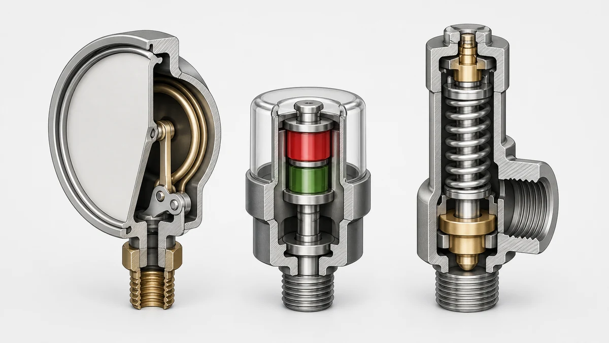
A mechanical pressure/vacuum gauge like the Qualitrol 050 is primarily a visual-indication device. Its core job is to give maintenance personnel a direct, readable snapshot of the gas or air pressure inside the transformer tank at the time of the reading. On sealed-tank designs, rising pressure during load indicates that internal processes are generating gas faster than the system can absorb it; a vacuum reading can indicate a cooling fluid volume loss or an improperly sealed tank. Neither condition is safe to ignore, and the gauge gives the first visible signal.
The 050 is also described by Qualitrol as a mechanical pressure-control device, meaning that, depending on the selected configuration, it can integrate switching or alarm functions — not just passive indication. This is a critical distinction for procurement: a gauge ordered without an alarm or switching option is purely a visual tool. A gauge ordered with those options becomes part of a protection or supervisory circuit, and its wiring, setpoints, and output format must then be coordinated with the overall scheme. What those setpoints are and what remote-signalling options are available for any specific order must be confirmed on the selected model; they are not universal across the product family.
The gauge does not relieve pressure. If tank pressure reaches a damaging level, a gauge reading tells a technician what happened; it does not protect the transformer or arrest the event.
What a Pressure Relief Device Does — and Where Indication Fits In
The Qualitrol LPRD is a mechanical relief device, meaning it performs a physical action: it opens at a defined pressure differential to vent transformer tank overpressure to atmosphere, protecting the tank from catastrophic rupture. Qualitrol describes it as suitable for both transformers and load tap changers. Its function is entirely different from a gauge — it is an intervention, not an observation.
Indication is optional on the LPRD. Qualitrol describes local-operation indication as an available feature, meaning the device can be configured to flag visually that it has operated. This is practically important for field inspection: a tripped LPRD without a local indicator requires comparing serial oil sampling or pressure readings before and after a suspected event to confirm whether the device actually opened. An indicator flag eliminates that ambiguity during a post-event walkthrough.
The alarm-switch arrangement is also optional. Without it, a relief event generates no automatic signal to a control room or SCADA system. Whether that is acceptable depends on the transformer's supervision and protection philosophy — a fully attended substation with frequent inspection rounds may tolerate a flag-only setup; a remote or unattended installation should have the alarm contact wired into a monitoring system.
Qualitrol explicitly states that the LPRD is not a substitute for a project-defined monitoring or protection scheme. This is not boilerplate — it describes a real functional gap. A pressure relief device prevents a mechanical failure; it does not diagnose the cause, log the event, or initiate a controlled de-energization. A complete protection scheme uses the LPRD alongside gas-in-oil monitoring, temperature protection, and differential relaying.
The Functional Distinction That Drives Selection
The gauge and the pressure relief device are not redundant or interchangeable. They address different points on the failure timeline.
The gauge provides continuous information between relief events. An engineer who sees the gauge reading trending upward over successive inspections has actionable data: gas generation is occurring, and the trend tells them something about rate and severity before the tank pressure ever reaches the relief threshold. That trend information disappears if the only installed device is the LPRD. Conversely, a gauge cannot prevent the tank from reaching damaging pressure if the operator is not present to read it or does not act in time — the LPRD does.
The two devices are therefore complementary. On transformers where tank overpressure is a credible fault mode — internal arcing, severe winding insulation failure, thermal runaway — both a relief device and a monitoring/indication device belong in the design.
Configuration Dependencies You Must Resolve Before an RFQ
Neither device leaves the factory in a single fixed configuration. Both carry options that change their function, their interface requirements, and their cost.
For the Qualitrol 050, the options described by Qualitrol include configuration-dependent switching, alarm outputs, scale range, and remote-signalling capability. The scale range matters: a gauge scaled for sealed-tank nitrogen-blanketed transformers may not be appropriate for a free-breathing design where the operating pressure band is different. If remote signalling is selected, the gauge becomes a wired device with installation requirements — cable routing, terminal block space, and relay-room interface — that a purely visual indicator does not carry.
For the Qualitrol LPRD, the relevant configuration choices include whether local-operation indication is included and which alarm-switch arrangement is selected. The alarm switch arrangement affects the wiring and the protection relay input assignment. These cannot be retrofitted after installation without disassembling the device or replacing it.
The practical rule is that options must be resolved at the specification stage, not during installation. An RFQ that does not specify alarm switch type, scale, and remote-signal format will result in a device that may not integrate with the installed protection scheme.
Where These Devices Sit Relative to Other Transformer Instrumentation
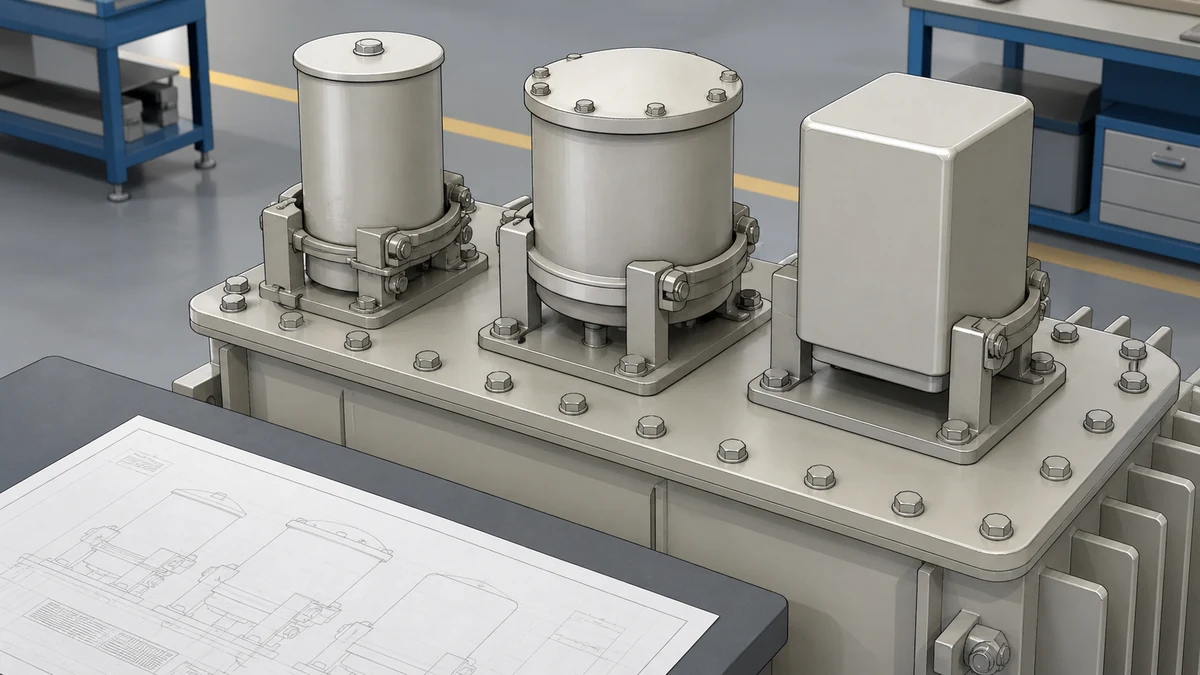
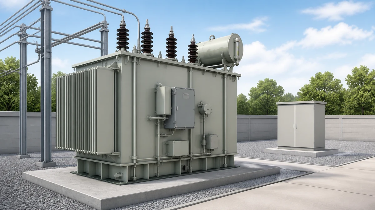
Transformer monitoring is a layered system. The pressure/vacuum gauge and the LPRD both address the tank pressure domain, but that domain is only one layer of a complete monitoring picture.
Gas analysis — dissolved gas analysis (DGA) of oil samples or an online DGA monitor — gives earlier and more diagnostic information about internal faults than pressure indication alone. Buchholz relays, used on conservator-equipped transformers, detect both the slow gas accumulation from developing faults and the rapid oil surge from more severe internal events, and they provide both alarm and trip outputs. Winding and oil temperature indicators address the thermal domain.
A transformer that has a pressure gauge and a relief device but no Buchholz relay and no DGA monitoring has one instrument layer covered and others missing. The selection process should map all accessory functions against the monitoring and protection requirements before specifying individual devices.
Standards and Evidence Boundaries
The Qualitrol product descriptions for the 050 and the LPRD provide functional descriptions and lists of available options. They do not publish default setpoints, alarm thresholds, or output contact ratings as universal values — those depend on the specific ordered configuration and must be confirmed from the device datasheet for the selected model number.
IEEE C57.12.00 covers general requirements for liquid-immersed distribution and power transformers and provides the framework within which pressure and temperature limits are defined. IEEE C57.135 addresses the application and installation of gas-over-oil equipment. IEC 60076 series standards cover similar ground for international applications. None of these standards specify which brand or model of accessory to use; they define the functional requirements that accessories must meet.
Field replacement decisions require checking that the replacement device matches the original in scale, configuration, contact rating, and process connection size. A device that is physically interchangeable may still be functionally incompatible if its alarm switch type or setpoint range differs from what the relay or SCADA system expects.
First, establish the tank design type: sealed tank with nitrogen blanket, free-breathing with silica gel breather, or conservator design. Pressure/vacuum gauge scale selection and operating range follow directly from this. A gauge appropriate for a nitrogen-blanketed sealed tank will typically cover both positive pressure and vacuum; a free-breathing design may operate consistently near zero gauge pressure, and scale selection should reflect that.
Second, determine the supervision philosophy. Is the transformer in an attended substation with scheduled inspection rounds, or is it remote and dependent on telemetry? Remote installations need alarm contacts wired to the monitoring system; attended installations may rely more on periodic visual inspection of flag indicators, but the choice should be explicit rather than an artifact of which options were left unchecked on the order form.
Third, identify all interface requirements before selecting options. Alarm contact type (normally open, normally closed, changeover), contact voltage and current rating, terminal block compatibility, and cable entry sizes must match what is already installed in the control system. Mismatches discovered during commissioning mean rework or device replacement.
Fourth, confirm the process connection size and gasket material against the transformer manufacturer's specification. The LPRD in particular has a defined mounting flange interface, and the replacement or addition of a relief device must match the transformer's tank penetration.
Fifth, for any alarm-generating accessory, coordinate with the protection relay engineer to confirm that the device's alarm output is wired to a relay input and that the relay logic treats it correctly — as an alarm, as a trip initiator, or as both, depending on the protection philosophy for that transformer.
Installation and Failure Risks
A pressure/vacuum gauge that has been subjected to a high-pressure event and then reset may have a distorted Bourdon tube or sticky mechanism that reads inaccurately without visible damage. Gauges should be calibrated on a defined schedule, and any gauge on a transformer that has experienced a pressure event should be replaced or bench-tested before being trusted.
Pressure relief devices can fail in two modes: failure to open (the device does not relieve when tank pressure exceeds the design threshold, resulting in tank rupture) and failure to close (the device opens and does not reseat, causing ongoing oil loss and moisture ingress). Both modes are serious. The LPRD's mechanical mechanism must be inspected for corrosion, debris, and free movement as part of any routine maintenance visit.
Indicator flags on the LPRD must be reset manually after an operation. A flag left in the operated position from a previous event is not informative on the next inspection; maintenance records should document when a flag was found operated and what investigation followed. If a relief device has operated and no investigation was conducted, the root cause of the pressure event is unknown and the transformer is at elevated risk.
Remote signalling from either device is only as reliable as the wiring between the device and the control room. Wiring continuity, terminal block integrity, and relay input status should be part of commissioning checks and periodic secondary injection testing.
FAQ
What is the difference between a transformer pressure relief device and a pressure/vacuum gauge?
A pressure relief device is a mechanical component that physically opens to vent excess pressure from the transformer tank when internal pressure reaches a specified threshold, protecting the tank from rupture. A pressure/vacuum gauge is an indication device that displays the current tank pressure on a dial for an observer to read. The gauge reports a condition; the relief device acts on it. They address different points in the fault sequence and are complementary rather than interchangeable.
What is the function of the Qualitrol LPRD in transformer protection?
Based on Qualitrol's own product description, the LPRD is a mechanical pressure-relief device for transformers and load tap changers. It opens to relieve overpressure from the tank and can be configured with a local-operation indicator to show that it has operated and with an alarm switch to send a signal to a monitoring or protection system. Qualitrol explicitly describes it as a relief and indication device, not a replacement for a complete monitoring or protection scheme.
What is a transformer pressure/vacuum gauge used for, and when does it need alarm contacts?
A pressure/vacuum gauge gives maintenance personnel a visual reading of tank pressure or vacuum at the time of inspection. Qualitrol describes the 050 as capable of configuration-dependent switching, alarm outputs, and remote signalling, depending on the selected model. Alarm contacts are needed when the operating philosophy requires an automatic signal to a control room or protection relay on an abnormal pressure condition, rather than relying solely on a technician reading the gauge during a scheduled inspection round. The need for alarm contacts is a project-specific decision driven by supervision philosophy and risk tolerance.
What is the process for verifying a replacement pressure/vacuum gauge is compatible with an existing installation?
Compatibility requires confirming that the replacement device matches the original on scale range, alarm switch type and contact rating, process connection size and gasket specification, and remote-signalling interface if that option is fitted. The scale range must suit the transformer's operating pressure band, which depends on tank design type. Alarm contact rating must match the relay input it drives. These specifications are model-specific and must be confirmed from the datasheet for the selected configuration, not assumed from the product family name.
What is the inspection interval for transformer pressure relief devices?
Specific inspection intervals depend on the owner's maintenance program, the transformer's service classification, and applicable utility or regulatory standards — no universal interval is specified within Qualitrol's product descriptions for the LPRD. What is clear from the device's function is that any transformer known to have experienced an internal pressure event should have its relief device inspected for proper reseating and its indicator flag documented before the transformer is returned to service. Industry maintenance practice typically includes visual inspection of all externally accessible accessories during routine maintenance outages.
LEO Chen
With more than 20 years of industry experience, LEO Chen has worked with major companies on switchgear, transformer components and medium-voltage equipment projects. He contributes practical guidance for engineers and sourcing teams, with a focus on clear selection criteria, application context and the information needed to prepare an informed RFQ. Connect with LEO on LinkedIn.