Send the request type, manufacturer, equipment model/year, part reference, ratings, quantity, destination, required date, and any drawing or photo notes. The SUVELL team will review the request.
Email: admin@suvell.com
Phone: +86 189 6871 1705
Factory: No.208 Wei 12 Rd, Yueqing Economic Development Zone, Wenzhou, Zhejiang, China
Transformer Gauge and Pressure-Relief Device Installation: Connections and Acceptance Checks
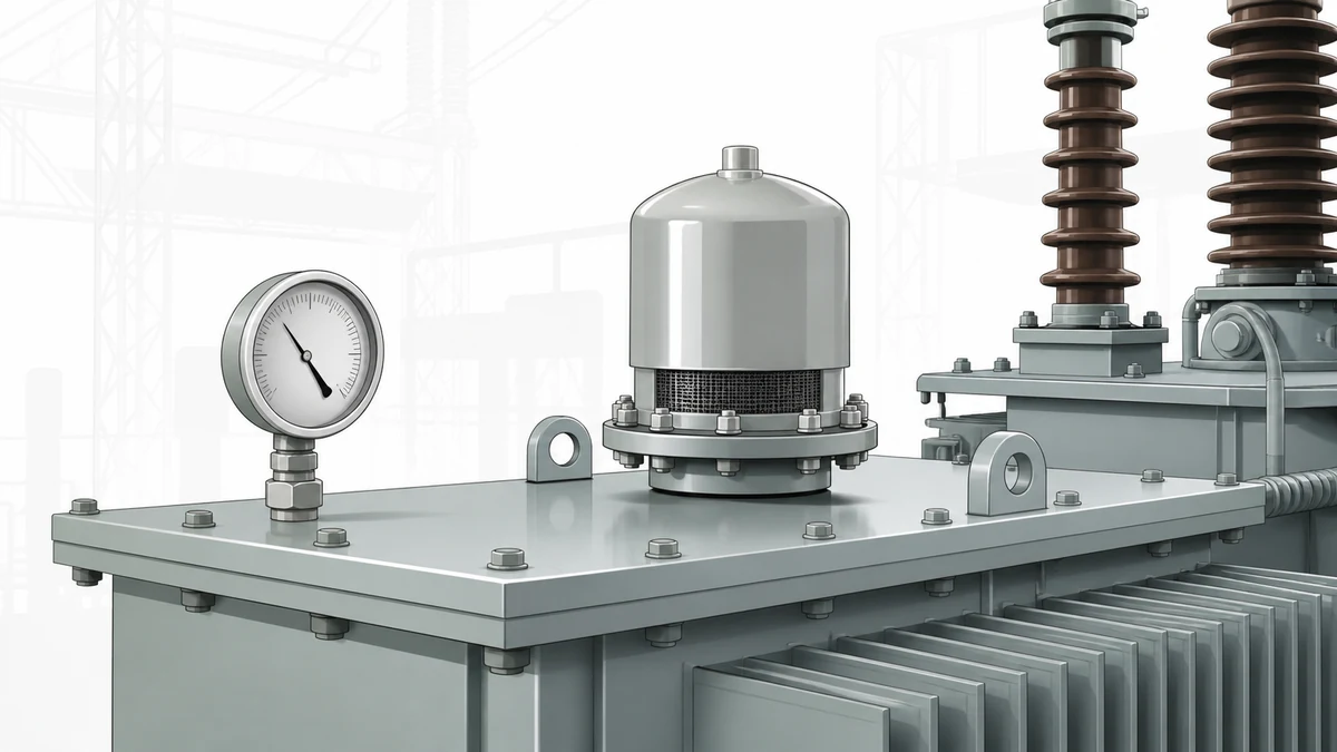
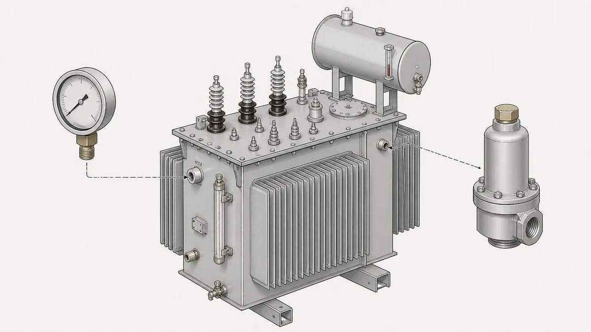
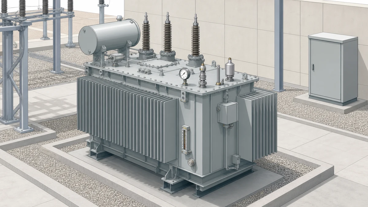
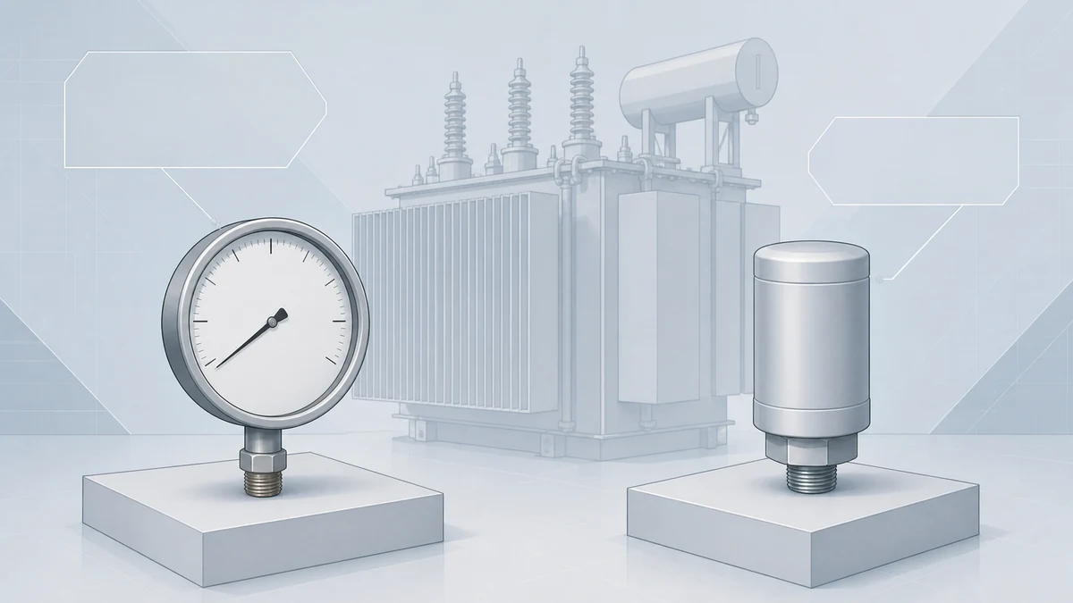
Pressure gauges and pressure-relief devices serve different transformer functions and need configuration-specific checks. This guide covers mounting connections, seals, electrical outputs, protection-scheme integration, and acceptance records, helping teams confirm the received device and its interfaces before installation and commissioning proceed.
Distinguish pressure indication from mechanical pressure relief and confirm which device configuration the transformer protection scheme requires.
Check the received ordering code, pressure range or relief setting, mounting connection, seals, and optional alarm outputs against approved project documents.
Verify terminal assignments and monitoring-system integration, then record device identity, inspection results, and any outstanding acceptance items.
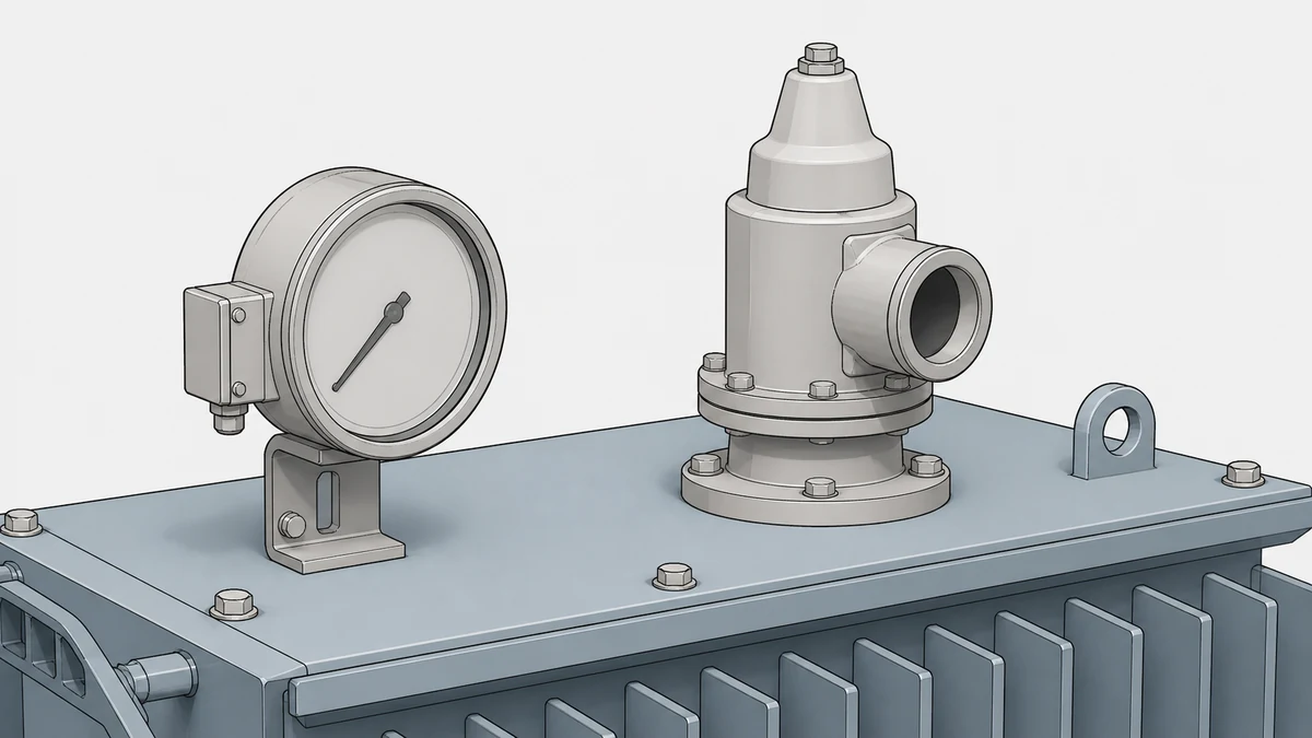
Transformer gauge installation succeeds when the selected device's configuration, interface, and rating are confirmed against the specific transformer project before any mounting or wiring begins. The Qualitrol 050 and LPRD serve distinct mechanical roles — pressure indication versus pressure relief — and neither substitutes for the other in a protection scheme. Every acceptance check described here is a documentation and verification activity; live-operation, switching, setpoint, torque, and adjustment actions are governed exclusively by the model-specific approved procedures for the installed device.
Feature
Qualitrol 050 (Pressure/Vacuum Gauge)
Qualitrol LPRD (Large Pressure Relief Device)
Primary function
Mechanical visual indication and tank pressure control
Mechanical pressure relief for transformer and LTC tank
Why Functional Role Determines Installation Sequence
The 050 is a pressure/vacuum gauge: it provides continuous visual indication of tank pressure and, depending on the selected configuration, can switch an alarm or remote signal when a threshold is reached. It monitors and signals. The LPRD is a pressure-relief device: it opens mechanically when internal pressure exceeds a set threshold, venting to prevent a catastrophic tank failure. It acts.
Because these functions are different, their installation sequences, acceptance criteria, and interface dependencies are also different. Treating a gauge as a redundant check on a relief device, or vice versa, introduces a gap in the protection scheme. Confirm with the project protection engineer which devices are required, in which locations, before procurement.
Device Configuration Dependencies That Must Be Resolved Before Ordering
Qualitrol describes the 050 as having configuration-dependent switching, alarm, scale, and remote-signalling options. This means the specific part number or ordering code governs what the installed device can actually do. A unit ordered without a contact output cannot be wired into an alarm circuit later without replacement or modification. Similarly, the scale must match the operating pressure range of the transformer tank; a unit with the wrong scale provides misleading indication regardless of how correctly it is installed.
For the LPRD, Qualitrol describes optional local-operation indication and alarm-switch arrangements. An LPRD without an alarm switch provides no electrical signal to a relay or SCADA system when it operates. If the project monitoring scheme requires that signal, it must be specified at the ordering stage.
Both devices must have their rated pressures, electrical interface ratings, and approval routes confirmed against the project transformer specification and applicable standards before an RFQ is issued. Do not assume a previously purchased configuration matches a new transformer's requirements.
Pre-Installation Documentation Checks
Before any device is mounted, the following documentation must be on hand and reviewed against the transformer nameplate and protection scheme drawing:
Manufacturer's installation drawing and model-specific procedure for the exact part number received
Transformer flange or boss dimensions and thread or bolt-circle specification matching the device's connection interface
Rated operating pressure and vacuum range of the transformer tank versus the device's indicated scale and rated opening pressure (LPRD)
Electrical interface ratings: contact voltage and current ratings for any switching or alarm output, verified against the relay or monitoring system input specification
Approval or certification route required by the project (e.g., UL, CSA, IEC) confirmed for the specific device received
Any project-specific setpoints pre-confirmed by the protection engineer; note that setpoints and adjustment procedures are governed by the model-specific approved procedure, not by this checklist
A mismatch at any of these points is a stop condition. Do not proceed to physical installation until discrepancies are resolved with the manufacturer or project engineer.
Mechanical Connection Acceptance Checks
The mounting interface between the device and the transformer tank is the first physical acceptance checkpoint. For the 050, the connection port thread form, size, and sealing method (gasket, O-ring, or thread sealant type) must match the transformer manufacturer's specification exactly. An incorrect thread engagement depth or an incompatible sealing method creates a leak path that may not be visible during initial commissioning but will manifest under thermal cycling.
For the LPRD, the flange bolt circle, bolt diameter, and gasket specification must be confirmed against the transformer's relief-port flange before mounting. Qualitrol's documentation for the specific LPRD model governs bolt torque sequence and values; applying generic fastener torque without reference to the model procedure risks both under-sealing and distortion of the seating face.
Acceptance checks at this stage:
Device part number on the received unit matches the purchase order and the project's approved configuration
Flange or port dimensions verified by measurement against the drawing, not assumed from prior experience
Gasket or sealing element is the specified type and is undamaged
No physical damage to the device body, indicator window, or connection interface visible on receipt inspection
Orientation requirement (if any) confirmed — some gauges and relief devices have a required mounting orientation for correct operation or drainage
Electrical Interface and Wiring Acceptance Checks
For any 050 configuration that includes switching, alarm, or remote-signalling outputs, and for any LPRD with an alarm-switch arrangement, the electrical interface requires independent verification before energisation of the secondary circuit.
The contact ratings published in the manufacturer's data for the specific configuration must be compared against the relay input or monitoring system input specification. Exceeding the contact's rated voltage or current, or applying AC to a DC-rated contact (or the reverse), damages the contact and may produce intermittent operation that is difficult to diagnose in service.
Wiring acceptance checks:
Terminal identification confirmed against the manufacturer's wiring diagram for the received model; do not use a generic diagram from a different variant
Cable type, size, and segregation confirmed against the project's secondary wiring specification
All terminals torqued to the manufacturer's specified value (model-specific procedure governs this)
Continuity and insulation resistance of the wiring to the relay panel confirmed before connection to the device terminals
Contact polarity and normally-open versus normally-closed configuration confirmed against the relay scheme drawing
Any screening or earthing requirement for the cable confirmed and implemented per the project specification
If the 050 is configured with remote-signalling output rather than a simple contact, the signal type (analogue, digital, protocol) and its interface requirements are additional confirmation points before wiring.
Interface with the Transformer Protection and Monitoring Scheme
Neither the 050 nor the LPRD replaces a project-defined monitoring or protection scheme, as Qualitrol states explicitly for the LPRD and the 050's configuration dependency implies for the gauge. This means the acceptance test cannot be completed by checking the device in isolation; it requires confirming how the device connects into the overall scheme.
For the 050 with switching or alarm output: confirm that the alarm point appears correctly in the relay or SCADA system, that the annunciation label matches the device and its location on the transformer, and that any trip or alarm logic driven by the contact has been reviewed by the protection engineer and accepted as part of the protection scheme review — not assumed from a template.
For the LPRD with alarm switch: confirm the same points. Additionally, confirm whether the project requires any specific test of LPRD alarm-switch operation at commissioning, and who holds authority to perform that test. This is a procedural escalation point, not a field improvisation.
If either device has a visual indicator (the 050's pressure/vacuum scale, the LPRD's local-operation indicator), confirm that the indicator is readable from the intended inspection vantage point and that the inspection interval and record format have been defined in the maintenance plan.
Commissioning Handoff and Acceptance Record
A device that passes all connection and documentation checks must be formally accepted before the transformer is energised. The acceptance record should capture:
Device type, manufacturer, model number, and serial number
Date of receipt inspection, installation inspection, and wiring verification
Name and role of the person performing each check
Any non-conformances identified, their disposition, and the authority who accepted the disposition
Reference to the model-specific installation procedure used
Outstanding items, if any, with a clear statement of whether they are hold points or witness points before energisation
Do not substitute a general commissioning sign-off for device-specific acceptance records. Pressure-related devices on a transformer tank are safety-relevant; traceability to the specific checks performed is required for both warranty purposes and incident investigation.
Procurement and RFQ Decision Inputs
Before issuing an RFQ for either device — whether for a new installation or a replacement — the following data must be in hand:
For the Qualitrol 050: the required scale range, the need for switching or alarm contacts and their ratings, whether remote signalling is required and in what form, the transformer tank port thread or connection specification, the required approval route, and any project environmental rating (temperature range, ingress protection).
For the Qualitrol LPRD: the transformer tank relief-port flange specification, the required relief pressure (confirmed by the transformer manufacturer), whether a local-operation indicator is required, whether an alarm-switch arrangement is required and its contact rating, and the required approval route.
In both cases, if the procurement is a like-for-like replacement of a failed or life-expired device, confirm that the original specification is still valid for the current transformer condition and that no protection scheme changes have been made since the original device was installed. A direct part-number replacement is appropriate only when those conditions are verified.
—
FAQ
What is the difference between a pressure/vacuum gauge and a pressure relief device on a transformer?
A pressure/vacuum gauge (such as the Qualitrol 050) provides visual indication of the current internal pressure or vacuum in the transformer tank and, depending on configuration, can generate a switching or alarm signal when pressure reaches a threshold. A pressure relief device (such as the Qualitrol LPRD) is a mechanical device that opens automatically when internal pressure exceeds a set value, physically venting the tank to prevent catastrophic failure. One monitors and signals; the other acts. They serve different functions in the protection scheme and are not interchangeable.
What is the Qualitrol 050 and what configurations are available?
The Qualitrol 050 is a mechanical transformer-tank pressure-control and visual-indication device described by Qualitrol as having configuration-dependent switching, alarm, scale, and remote-signalling options. The available configurations determine what the installed device can do in service. The specific model's documents, ratings, setpoints, and interfaces must be confirmed for each transformer project; the 050 is not a single fixed product but a product with selectable features that must be specified at the ordering stage.
What is the Qualitrol LPRD and when is it used?
The Qualitrol LPRD is a mechanical pressure-relief device designed for transformers and load tap changers. Qualitrol describes it as offering optional local-operation indication and alarm-switch arrangements. It is used when the transformer specification or applicable standard requires a large-format pressure relief device at a specific flange port. The LPRD does not replace a project-defined monitoring or protection scheme; it is one component within that scheme and its specification — particularly the required opening pressure and alarm interface — must be confirmed against the transformer and protection system design before procurement.
What is required before transformer gauge installation begins?
Before installation begins, the device part number and configuration must be confirmed against the project specification; the physical connection interface (thread, flange) must be verified against the transformer drawing; the electrical interface ratings must be confirmed against the relay or monitoring system inputs; the required approval route must be confirmed for the received unit; and the model-specific manufacturer installation procedure must be on hand. Any discrepancy between the received device and the project requirement is a stop condition requiring resolution before physical installation proceeds.
What is the acceptance record needed after transformer monitoring device installation?
The acceptance record must capture the device type, manufacturer, model number, and serial number; the transformer identification; the dates and responsible individuals for receipt inspection, installation inspection, and wiring verification; any non-conformances and their dispositions; the model-specific procedure used; and any outstanding hold or witness points before energisation. A general commissioning sign-off does not substitute for a device-specific record, because pressure-related devices on a transformer are safety-relevant and require traceability for warranty and incident investigation purposes.
LEO Chen
With more than 20 years of industry experience, LEO Chen has worked with major companies on switchgear, transformer components and medium-voltage equipment projects. He contributes practical guidance for engineers and sourcing teams, with a focus on clear selection criteria, application context and the information needed to prepare an informed RFQ. Connect with LEO on LinkedIn.