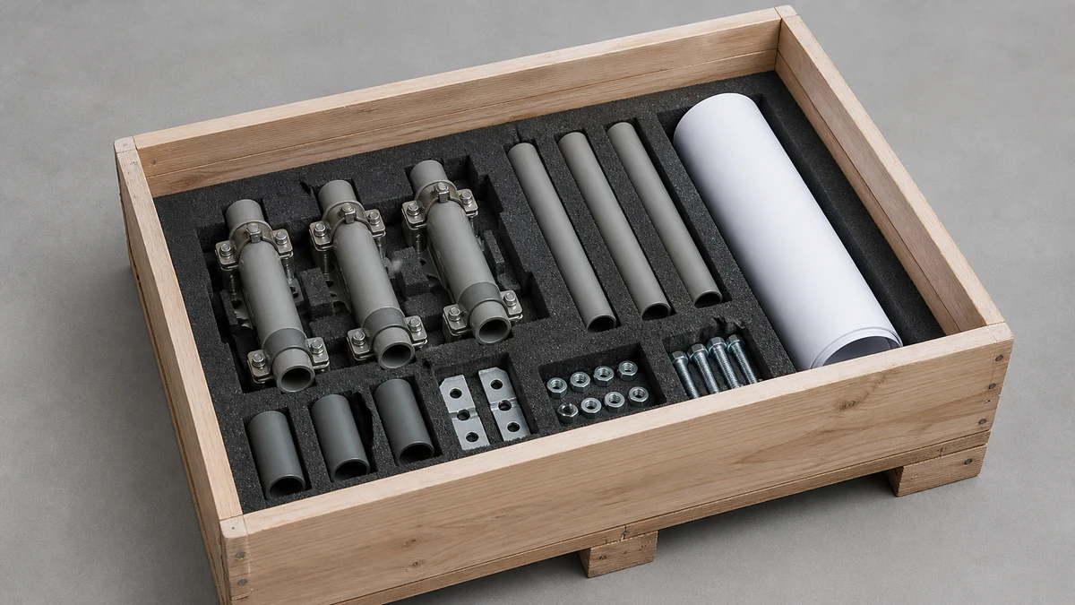
Send the request type, manufacturer, equipment model/year, part reference, ratings, quantity, destination, required date, and any drawing or photo notes. The SUVELL team will review the request.
Email: admin@suvell.com
Phone: +86 189 6871 1705
Factory: No.208 Wei 12 Rd, Yueqing Economic Development Zone, Wenzhou, Zhejiang, China
Transformer Fuse Holder Inspection: Contact Heating, Seals, and Mechanical Damage
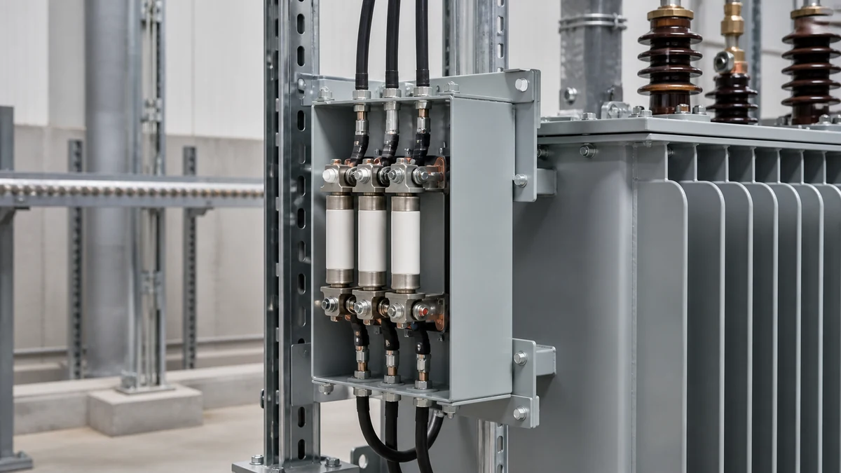
Fuse holder condition depends on the contact interface, enclosure seals, and mechanical support. This inspection guide follows evidence of heating, moisture ingress, and physical damage, then lists the fuse dimensions, ratings, and mounting details needed to specify a suitable replacement assembly.
Review thermal records and inspect fuse clips and ferrules for oxidation, pitting, and loss of contact spring tension.
Check gaskets, insulating surfaces, holder alignment, and mounting support for moisture evidence, tracking, cracks, or movement.
Specify the fuse dimensional series, electrical ratings, enclosure requirements, and mounting dimensions when sourcing a replacement holder.
Transformer fuse holder inspection is a structured visual, thermal, and mechanical review of the fuse clips, contact surfaces, enclosure seals, and structural mounting that together determine whether a fuse can interrupt fault current reliably. The inspection does not involve fuse coordination calculations — it identifies degradation that warrants cleaning, re-torquing, or outright replacement before a thermal or dielectric failure forces the decision. Getting this right before energization or during scheduled maintenance prevents the more expensive outcome: a fuse holder that fails to clear a fault cleanly, damages surrounding equipment, or allows arcing at a compromised contact.
—
Why Contact Condition Drives the Inspection
The fuse holder's clips and terminals are the first place degradation appears, and they are the last place many inspectors look carefully. A fuse clip transfers current across a mechanical interface. Any increase in contact resistance at that interface produces I²R heating that is disproportionate to the load current — small resistance increases at high current cause large thermal rises. Eaton's Bussmann series protective-device handbook identifies fuse terminals and clips as inspection considerations within a broader equipment-inspection context, reinforcing that these interfaces are active failure sites, not passive hardware.
The mechanism is straightforward. Oxidation or surface contamination raises interface resistance. Clip spring tension that has relaxed — from thermal cycling, over-insertion of a previous fuse, or simply age — reduces contact force and shrinks the effective contact area. Both conditions elevate resistance at the same point, and the heating is self-reinforcing: elevated temperature accelerates oxidation, which raises resistance further. A fuse holder running hotter than its surrounding bus or cable is already in a degraded state, even if the fuse itself measures within tolerance.
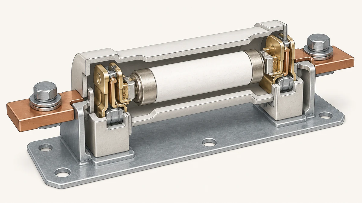
During inspection, the contact surfaces inside each clip should be examined for pitting, arc tracking, carbon deposits, or a dull oxidized appearance in place of the original bright metal finish. Clips that show visible spring relaxation — where the jaw opening has widened compared to an adjacent undamaged clip, or where the fuse seates loosely — need replacement, not cleaning. Cleaning a clip with inadequate spring tension restores surface finish without restoring clamping force, and the thermal problem returns.
Thermal imaging during a live circuit review is the most reliable single method for identifying elevated contact resistance before it reaches a visible state. A clip running more than approximately 10°C above an adjacent identical clip under the same load is worth investigating even if the surface appears clean. That threshold is a practical field reference, not a published standard criterion; the relevant comparison is always relative to identical hardware under the same current.
—
Enclosure Seals and Dielectric Integrity
Seal condition is a parallel inspection track, not a subordinate one. A fuse holder that passes contact inspection but has a compromised enclosure seal is still at risk — moisture ingress is the primary driver of creepage and flashover failures in medium-voltage fuse holders, and it operates silently until a dielectric event occurs.
The seal inspection covers the fuse cap or end-cap gaskets, the body-to-mounting interface, and any conduit or cable entry seal if the holder is enclosed. Gaskets that have hardened, cracked, compressed set below their design thickness, or show surface checking are no longer performing their sealing function even if no liquid water is visible. Silicone gaskets age more gracefully than neoprene or EPDM under thermal cycling, but none are indefinitely serviceable.
Internal moisture evidence includes white mineral deposits (efflorescence) on insulating surfaces, surface tracking paths that show a carbonized or chalky discoloration following a creepage route, and condensation residue visible when the enclosure is opened. Any of these is a replacement trigger for the holder assembly, not a cleaning item. Carbon tracking on a polymeric insulating body cannot be remediated by wiping — the surface resistivity along the track is permanently degraded, and re-energization creates a preferential path for flashover.
The dielectric condition of the insulating body itself — separate from the seal — also warrants inspection. UV degradation on outdoor holders produces a chalky surface bloom and micro-cracking that reduces the comparative tracking index over time. Medium-voltage holders that have been in outdoor service for more than ten years should be assessed against the original material specification, particularly if the installation is in a high-UV or coastal salt-fog environment.
—
Mechanical Damage and Structural Support
Mechanical inspection has two scopes: the holder body itself and the mounting structure that supports it. These are distinct failure modes with different consequences, and Eaton's site acceptance testing guidance — which covers visual and mechanical inspection items for medium-voltage equipment — explicitly includes verification of adequate fuse-holder mechanical support as part of documented acceptance criteria. That framing matters: mechanical support is a test item at acceptance, which means its degradation during service life is an inspection item at every subsequent review.
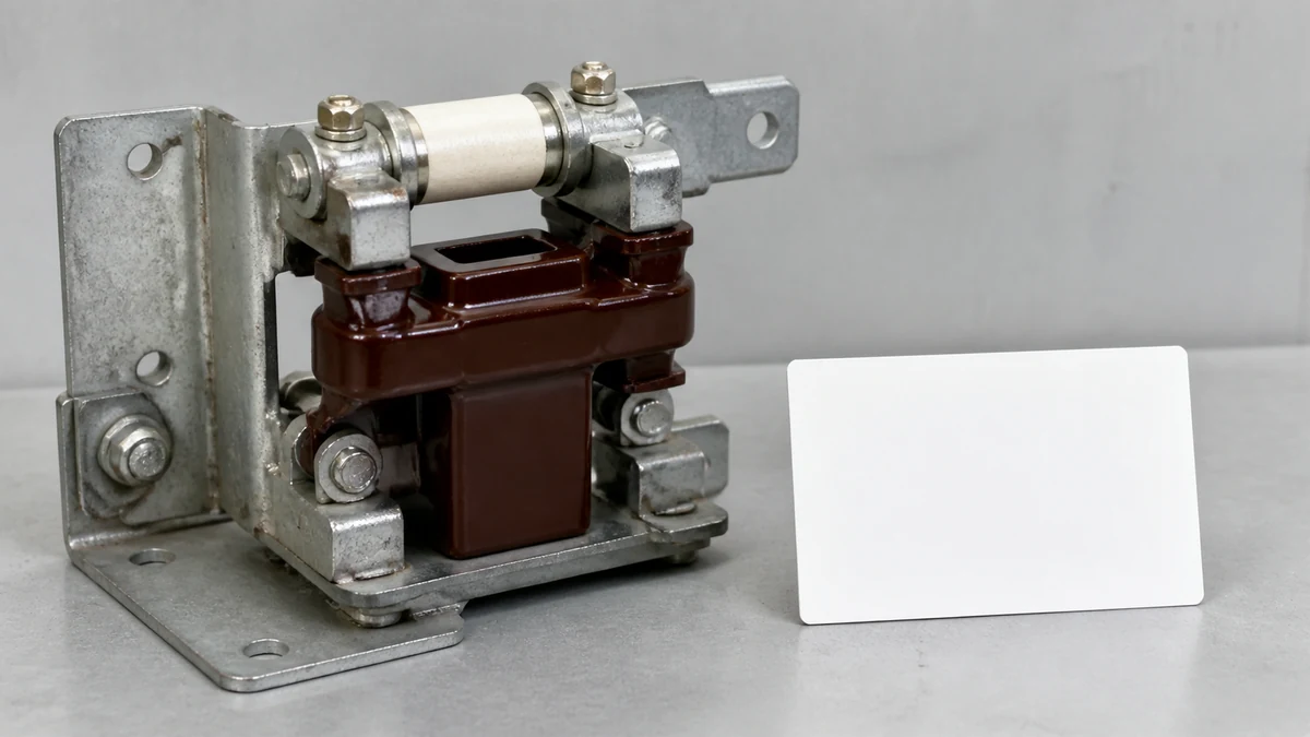
On the holder body, look for cracking at the clip-mounting bosses, deformation of the contact ferrule seats, chipped or broken insulator sheds on post-type holders, and signs of past mechanical impact (flat spots, scuff marks, crack initiations at stress concentrations). Polymer bodies that have taken impact damage may show no external crack while harboring internal delamination that reduces both mechanical strength and dielectric performance. If the installation history includes any nearby fault event — even one that the fuse cleared successfully — the holder should be treated as a candidate for replacement on the basis that electromagnetic force during interruption is significant and may have introduced damage not visible externally.
Mounting hardware inspection covers the integrity of the bracket or bus support, the torque condition of the fasteners (loose fasteners allow vibration-induced fretting at the contact interface), and the alignment of the holder relative to the bus. A holder that has shifted out of alignment imposes a side load on the fuse body when inserted, which stresses both the clip and the fuse ferrule. In three-phase installations, check that the phase spacing has not been reduced by any structural movement — reduced clearance is a flashover risk independent of holder condition.
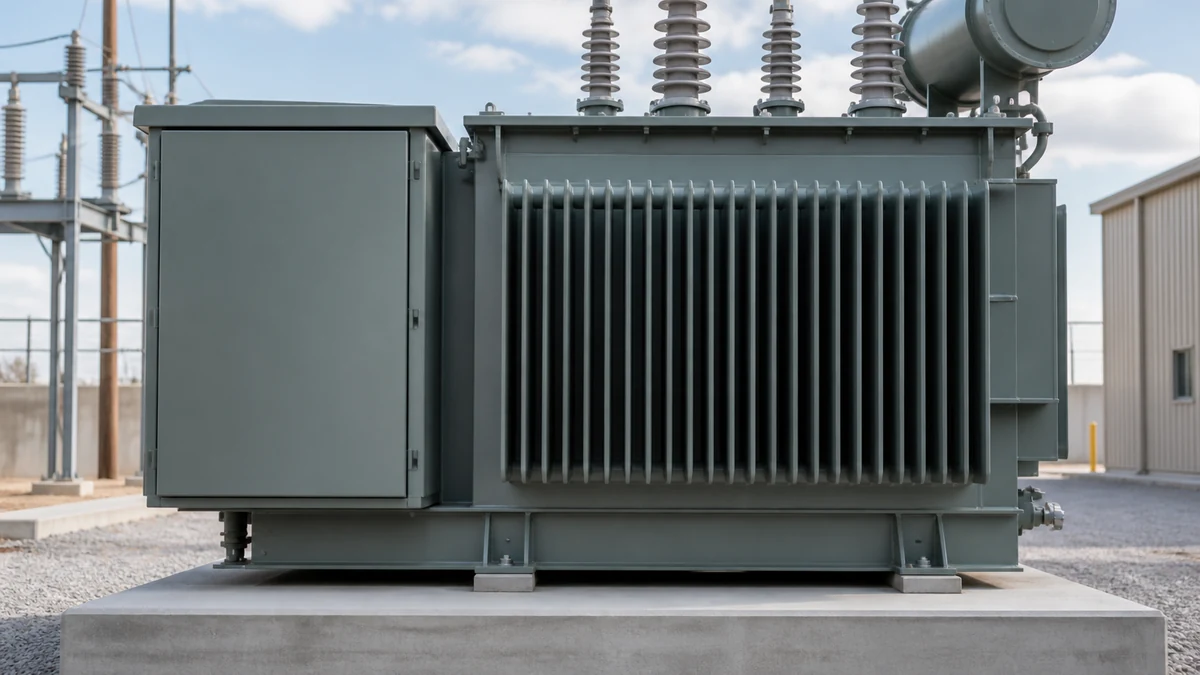
For pad-mounted or underground installations, inspect the mounting surface for moisture ingress from below, corrosion of the mounting hardware, and any evidence of settling or movement in the enclosure structure. Movement in the base creates misalignment and can fracture insulating standoffs that are not visible until the holder is removed.
—
Inspection Workflow and Replacement Triggers
A practical inspection follows a defined sequence so that findings at one stage inform the depth of review at the next, and so that the documented record supports future trend analysis. Eaton's site acceptance guidance supports a documented inspection record for medium-voltage equipment; applying that same discipline to service-interval inspections produces a baseline that makes condition deterioration identifiable over time rather than apparent only at failure.
**Pre-inspection (de-energized and isolated, verified by appropriate means):**
– Confirm the circuit is de-energized, isolated, and grounded per site LOTO procedure before opening any enclosure or touching any component.
– Photograph the holder assembly before disturbing it; document phase identification, fuse labeling, and any pre-existing anomalies.
**Thermal record review:**
– If thermal imaging data from the last inspection or a recent live-circuit scan is available, review it before the physical inspection to direct attention to flagged phases.
**Contact and clip inspection:**
– Remove the fuse and inspect the clip interior surfaces for pitting, oxidation, arc tracking, and carbon deposits.
– Assess clip spring tension by comparing jaw width and resistance to insertion across phases; replace clips showing relaxation.
– Inspect fuse ferrule contact surfaces for corresponding damage — a damaged ferrule indicates historical overheating at that interface.
**Enclosure and seal inspection:**
– Inspect all gaskets for hardening, cracking, or compression set; replace any gasket that does not return to its uncompressed profile.
– Examine insulating surfaces for tracking, efflorescence, or carbonization; any tracking is a replacement trigger.
– Check for moisture evidence inside the enclosure.
**Mechanical inspection:**
– Inspect the holder body for cracking, impact damage, and shed condition.
– Verify mounting hardware torque and bracket integrity.
– Confirm phase spacing and holder alignment.
**Replacement triggers** (any one is sufficient):
– Carbon tracking on any insulating surface
– Clip spring tension below design (verified by jaw width comparison or insertion force)
– Gasket failure with evidence of moisture ingress
– Cracking of holder body at any location
– Thermal imaging showing greater than approximately 10°C differential between phases under equal load, without an alternative explanation
– Service history that includes a nearby fault event of unknown magnitude
—
Data Needed Before an RFQ or Replacement Decision
Ordering a replacement fuse holder without the right parameters results in a part that fits neither the fuse nor the enclosure, and procurement records that were adequate for initial commissioning often omit dimensions needed for like-for-like replacement years later.
**Fuse class and dimensional series** — e.g., Class R, Class J, current-limiting HH, or utility expulsion type; the holder is designed around the fuse body dimensions and the contact geometry is not interchangeable across classes.
**Voltage rating** — the holder's rated voltage must meet or exceed the system voltage; a holder rated below system voltage is not a code-compliant replacement regardless of fuse rating.
**Continuous current rating** — the holder current rating must equal or exceed the fuse rating; derating for elevated ambient temperature applies to the holder as well as the fuse.
**Interrupting rating compatibility** — the holder must be rated to withstand the forces and energy of the fuse's interrupting rating; this is a holder structural specification, not a coordination calculation.
**Enclosure ingress protection rating** — match or exceed the original IP or NEMA rating; downgrading the enclosure rating changes the maintenance interval and the suitability for the installation environment.
**Mounting configuration** — bolt pattern, stud size, phase spacing, and bus bar interface dimensions; measure from the removed holder, not from memory or a commissioning drawing that may not reflect field modifications.
**Material specification for the insulating body** — particularly for outdoor or high-UV environments; verify that the replacement material has a comparable or superior comparative tracking index and UV resistance rating.
If the original manufacturer or part number is unreadable or unavailable, the dimensional and rating data above is sufficient for a cross-reference against current product lines. Confirm the cross-reference with the replacement holder manufacturer before ordering; dimensional similarity across classes does not guarantee contact geometry compatibility.
—
FAQ
What is the most common cause of fuse holder overheating?
Elevated contact resistance at the clip-to-ferrule interface is the most common cause. It results from oxidized contact surfaces, relaxed clip spring tension, or a combination of both. The resistance increase is small in absolute terms but produces disproportionate heating at load current levels, and the heating accelerates oxidation in a self-reinforcing cycle. Thermal imaging during live-circuit operation is the most reliable way to detect this before it reaches a visually obvious state.
What is the difference between a fuse holder and a fuse carrier?
A fuse holder is the fixed assembly — the clips, insulating body, and mounting hardware — that remains in place when the fuse is removed. A fuse carrier (also called a fuse base or fuse block in some product lines) refers to a withdrawable or modular subassembly into which the fuse clips are integrated, designed to be extracted as a unit. The inspection criteria for contact condition, seal integrity, and mechanical support apply to both configurations; the difference is in the replacement unit — a degraded clip set in a holder requires clip or holder replacement, while a degraded carrier can sometimes be replaced without disturbing the fixed bus connection.
What is the inspection interval for transformer fuse holders?
There is no single universal interval that applies across all installations. A practical baseline for indoor medium-voltage equipment in a clean environment is annual visual inspection with thermal imaging on a live circuit, combined with a detailed contact and seal inspection every three to five years or following any fault event. Outdoor, coastal, high-humidity, or high-cycling installations warrant shorter intervals. Eaton's site acceptance guidance establishes the documentation standard for the initial inspection; subsequent intervals should be defined in the site maintenance plan and adjusted based on condition trends observed in the inspection record.
What is the correct torque for fuse holder mounting fasteners?
The torque specification is specific to the fastener size, material, and the holder mounting interface, and must come from the holder manufacturer's installation documentation for the specific product. Applying a generic torque value risks either under-torquing (allowing fretting and vibration-induced loosening) or over-torquing (cracking the insulating body or stripping the mounting boss). If the original documentation is unavailable, contact the manufacturer with the part number before applying any torque value from a general reference.
What is carbon tracking on a fuse holder and why does it require replacement?
Carbon tracking is a carbonized conductive path formed on the surface of an insulating body by electrical discharge — typically initiated by surface contamination or moisture — that partially bridges a creepage distance. The carbon deposit has much lower surface resistivity than the base insulating material, which means it provides a preferential path for subsequent arcing. Unlike oxidation on a metal contact surface, carbon tracking on a polymer or ceramic insulating surface cannot be remediated by cleaning or surface treatment; the base material's surface resistivity along the track is permanently reduced. Re-energizing a holder with visible carbon tracking creates a high probability of flashover along the existing track, which is why any visible tracking is an unconditional replacement trigger.
LEO Chen
With more than 20 years of industry experience, LEO Chen has worked with major companies on switchgear, transformer components and medium-voltage equipment projects. He contributes practical guidance for engineers and sourcing teams, with a focus on clear selection criteria, application context and the information needed to prepare an informed RFQ. Connect with LEO on LinkedIn.