Send the request type, manufacturer, equipment model/year, part reference, ratings, quantity, destination, required date, and any drawing or photo notes. The SUVELL team will review the request.
Email: admin@suvell.com
Phone: +86 189 6871 1705
Factory: No.208 Wei 12 Rd, Yueqing Economic Development Zone, Wenzhou, Zhejiang, China
Three-Position Switch vs Load Break Switch: Functions, Interlocks, and Selection Boundaries
Three-position switch and load break switch describe different attributes and can refer to the same RMU module. This guide separates operating states from load-switching capability and explains why earthing, fuse integration, door access, and mechanism interlocks must be checked against the installed configuration.
Three-position describes connected, open, and earthed states, while load break describes switching duty; one RMU module can provide both functions.
A three-position sequence alone does not establish load-breaking capability; check the documented duty for the exact switchgear configuration.
Compare earthing, fuse, door, and mechanism interlocks together with the enclosure and operating shaft when selecting or replacing the module.
In medium-voltage RMU and compact switchgear selection, the phrase **three position switch vs load break switch** can be confusing because the two terms do not always describe the same type of attribute. A **three-position switch** describes a switching arrangement or mechanism position set—typically connected, open, and earthed. A **load break switch** describes an equipment role: a device intended to make and break load current within its certified application.
That means the comparison is not always “device A versus device B.” In many RMU designs, a load-break switch function may itself be built as a three-position switch disconnector and earthing switch. The practical selection question is therefore: **what function is required, what interlocks are present, and what operating duty has been verified for the installed switchgear configuration?**
Functional meaning of a three-position switch
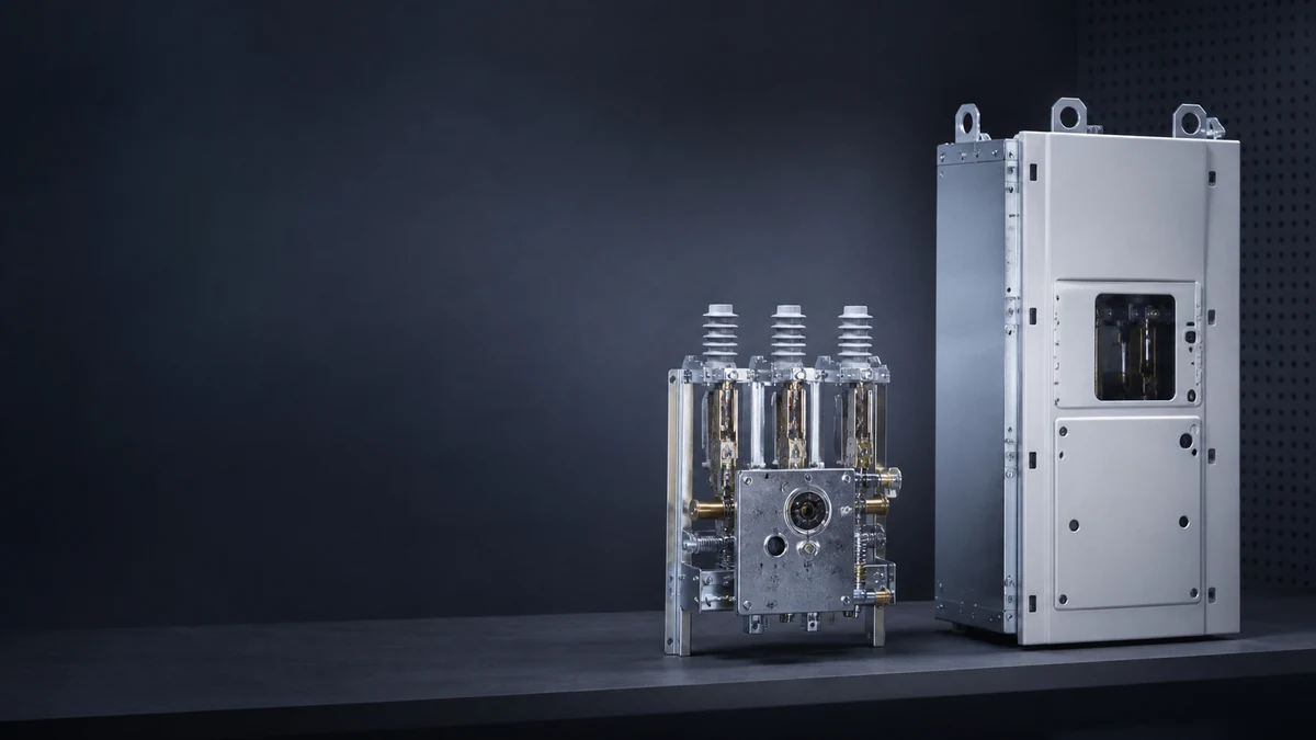
A three-position switch in MV switchgear is commonly understood as a switch disconnector, or a disconnector combined with an earthing switch, arranged around three defined positions. ABB describes this type of arrangement with **LINE–OPEN–EARTH** positions. In other catalog language, the same functional idea may appear as **close–open–earthed** positions.
The important point is that “three-position” refers to the switching state sequence and the integrated relationship between the line side, isolation position, and earthing position. In RMU applications, this construction helps simplify operation because the operator is not managing completely independent line and earthing devices without coordinated position logic.
A three-position switch is typically associated with:
A normal service position connected to the line or feeder circuit.
An open or isolated position.
An earthed position for grounding the relevant circuit section.
Mechanical position indication and operating sequence control.
Interlocking intended to prevent incompatible operations.
However, the term alone does not prove the device’s interrupting capability. A three-position disconnector may be part of a load-break module, or it may serve another switching and isolation role depending on the panel design and certification.
Functional meaning of a load break switch
A load break switch is defined by its switching duty. In MV distribution, it is used as a device role for making and breaking load current under specified conditions. Schneider identifies the RL-Series as a three-phase load-break switch or sectionalizer for medium-voltage distribution, which illustrates that “load break switch” is an application and equipment role, not merely a mechanism shape or position count.
For RMU selection, this means the label “load break switch” must be read together with:
The actual switchgear module configuration.
The medium used for switching and insulation, where applicable.
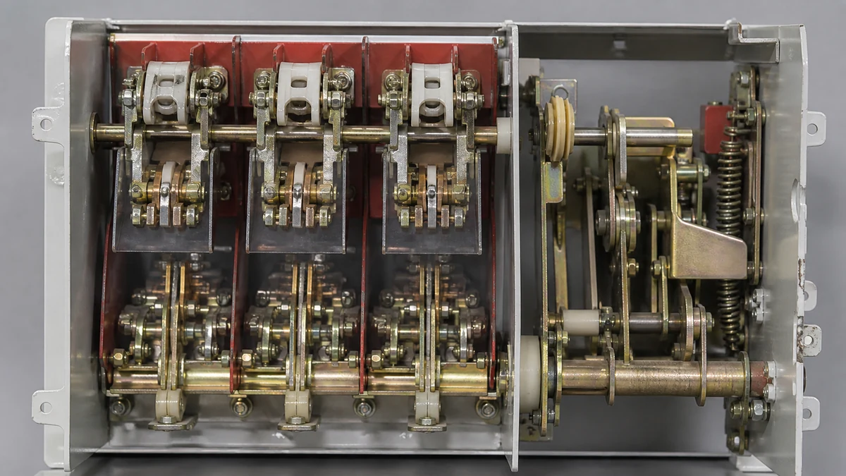
The operating mechanism and interlock design.
The intended feeder, transformer, sectionalizing, or ring-network duty.
The manufacturer’s tested and certified ratings.
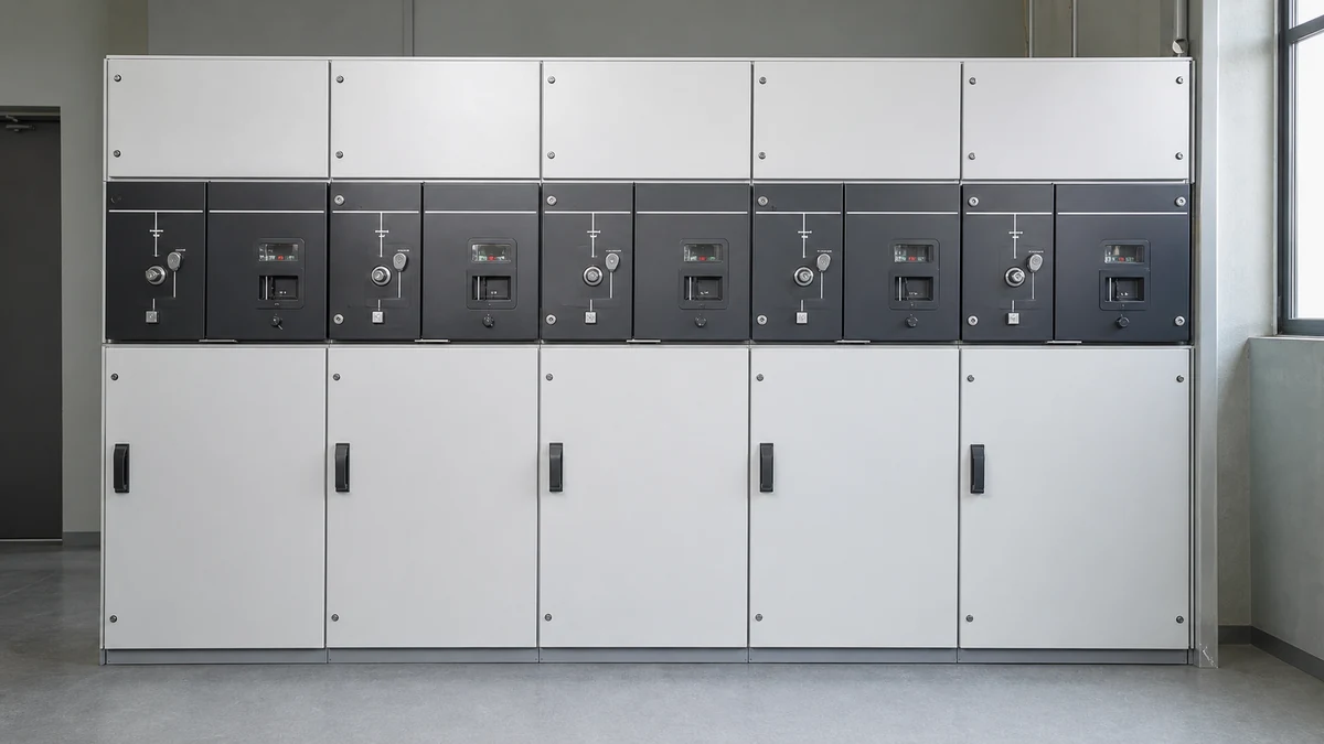
The enclosure, door, cable compartment, and earthing arrangement.
A load break switch may be integrated into a compact RMU panel as a three-position switch disconnector and earthing switch. In that case, the device is both a load-break functional module and a three-position switching arrangement.
Three-position switch vs load break switch: not a one-to-one contrast
The most common misunderstanding in **three position switch vs load break switch** comparisons is treating the terms as mutually exclusive. They are better understood as two different classification layers.
Comparison point
Three-position switch
Load break switch
Main meaning
Describes switch positions and operating sequence
Describes switching duty and equipment role
Typical positions
Line/closed, open, earth/earthed
May be open/closed only or may be integrated with earthing, depending on design
RMU relevance
Common in compact RMUs because isolation and earthing are coordinated
Common feeder or transformer switching function in RMUs
Key selection concern
Position logic, isolation, earthing, and interlocks
Load-current switching capability and application duty
Can overlap?
Yes
Yes, a load-break module may use a three-position mechanism
ABB catalog evidence shows this overlap clearly: a load-break switch module may be described as a **three-position switch disconnector and earthing switch**, with close, open, and earthed positions. The same evidence also notes mechanism interlocking to prevent conflicting operations. Therefore, in an RMU, the correct question is often not “Which is better?” but “Is the required load-break function implemented through a compliant three-position module with the correct interlocks?”
Interlocks are central to the comparison
Interlocking is one of the main reasons three-position devices are widely used in RMU layouts. A compact RMU often places switching, isolation, fuse protection, cable access, and earthing functions close together. Without coordinated interlocks, incorrect operation could create unsafe or destructive conditions.
The supplied evidence identifies several interlock contexts:
ABB notes integration with fuses and panel earthing-switch interlocking.
ABB catalog language describes mechanism interlocking that prevents conflicting operations in a load-break switch module.
Schneider identifies door interlocks and configuration-dependent layouts.
Replacement or selection must retain the installed enclosure and interlock context, not just match a mechanism label.
In practical terms, this means interlocks should be reviewed at multiple levels:
1. **Mechanism interlocking** — prevents incompatible switching operations, such as attempting to move directly into an unsafe state.
2. **Earthing interlocking** — coordinates the earthing switch with line isolation and panel conditions.
3. **Fuse-related interlocking** — applies where fuse-switch combinations are used.
4. **Door and enclosure interlocking** — controls access to compartments based on switch position and installed layout.
5. **Panel-to-panel or system interlocking** — may apply in larger RMU or switchboard arrangements.
A buyer comparing MV switching devices should not evaluate the interrupter or operating handle alone. The interlock chain is part of the functional safety architecture of the complete panel.
Selection boundaries for RMU applications
For RMU selection, the boundary between a three-position switch and a load break switch depends on what problem the device must solve.
Choose or specify around the **three-position function** when the priority is:
Clear operating states: connected, open, and earthed.
Integrated isolation and earthing sequence.
Reduced risk of conflicting operator actions.
Compatibility with RMU compartment access logic.
Coordinated earthing-switch interlocking.
Choose or specify around the **load-break function** when the priority is:
Switching energized load circuits.
Feeder or transformer switching duty.
Sectionalizing a medium-voltage distribution circuit.
Matching the operating duty required by the network design.
Ensuring the device is certified for the actual load-breaking application.
In many RMU projects, both requirements apply. A feeder unit may need a load-break switch function and a three-position operating sequence. A transformer protection unit may combine a load-break switch with fuses and interlocking. A sectionalizing unit may be called a load-break switch or sectionalizer depending on the manufacturer’s product family and application layout.
Why configuration matters more than the mechanism label
A mechanism label can be misleading if it is separated from the installed switchgear. Schneider’s documentation emphasizes door interlocks and configuration-dependent application layouts. This matters because two devices with similar switch labels may not be interchangeable if they belong to different enclosures, access systems, or interlock schemes.
Whether the original panel used a three-position disconnector and earthing switch.
Whether the load-break duty is required for that feeder.
Whether the operating shaft, handle interface, and position indication correspond to the enclosure.
Whether the cable compartment door interlock remains valid.
Whether fuse integration or earthing-switch interlocking is part of the original design.
Whether the complete assembly remains compliant after replacement.
A buyer should avoid selecting an MV switching device only because it appears to have the same number of positions or a similar operating handle. RMU switching devices are part of a coordinated enclosure system.
Practical comparison for consideration-stage buyers
At the consideration stage, the best approach is to define the required function before comparing product names.
If the project is a new RMU selection, ask:
Is the panel a ring feeder, transformer feeder, metering unit, sectionalizer, or another application layout?
Does the circuit require load-current switching?
Is an integrated earthing position required?
Is fuse integration part of the design?
What interlocks are required between the switch, earthing function, fuses, cable compartment, and door?
Does the manufacturer describe the module as a load-break switch, switch disconnector, disconnector and earthing switch, or sectionalizer?
Are the certified ratings and duties documented for the exact configuration?
If the project is replacement or spare-parts selection, ask:
What is the installed switchgear model and panel configuration?
What operating mechanism is fitted?
Are the LINE–OPEN–EARTH or close–open–earthed positions mechanically coordinated?
Does the replacement preserve door and enclosure interlocks?
Does it preserve earthing-switch interlocking?
Does it preserve fuse-related interlocking where applicable?
Is the component being replaced part of a load-breaking function or only an isolation/earthing function?
This approach avoids the common mistake of comparing a three-position switch and a load break switch as if they are always separate product families.
Application boundary: when the terms overlap
The terms overlap when a load-break switch module is built as a three-position switch disconnector and earthing switch. This is common in compact RMU architecture because the device can provide load switching, isolation, and earthing sequence management within one coordinated module.
In that case:
“Load break switch” tells you the module’s switching role.
“Three-position switch” tells you the mechanism’s position logic.
“Switch disconnector and earthing switch” tells you the isolation and grounding arrangement.
“Interlocked mechanism” tells you that conflicting operations are mechanically restricted.
This overlap is why product descriptions should be read carefully. One manufacturer may emphasize the load-break switch role, while another may emphasize the three-position switch disconnector construction.
Application boundary: when the terms should not be treated as equivalent
The terms should not be treated as equivalent when the three-position device is not documented for the required load-breaking duty, or when a load-break switch is part of a different enclosure and interlock arrangement.
A three-position position sequence alone does not prove that a device is suitable for interrupting a specific load duty. Likewise, a load-break switch name alone does not prove that it includes the same earthing function, door interlock, fuse coordination, or RMU compartment arrangement as the device being replaced.
The safest comparison boundary is the complete documented assembly:
Device role.
Position sequence.
Interlock scheme.
Enclosure layout.
Operating duty.
Manufacturer certification.
Installed switchgear context.
Common selection mistakes to avoid
A comparison between three-position switches and load break switches should avoid several mistakes.
First, do not assume that every three-position switch has the same function. Some are switch disconnectors with earthing capability, while others are part of load-break modules.
Second, do not assume that every load break switch has the same interlock structure. Door interlocks, earthing interlocks, fuse integration, and enclosure access logic vary by configuration.
Third, do not select replacement parts by appearance alone. Similar operating handles or position indicators do not confirm compatibility.
Fourth, do not compare devices using fixed ratings unless those ratings are taken from the exact manufacturer documentation for the exact configuration. In RMU selection, ratings and duties must be verified rather than inferred.
Fifth, do not ignore the installed enclosure. MV switching devices are not isolated components in the practical sense; they operate inside a mechanical and electrical safety system.
FAQ
What is a three-position switch in MV switchgear?
A three-position switch is a switching arrangement with three defined states, commonly described as LINE–OPEN–EARTH or close–open–earthed. It is often used as a switch disconnector and earthing switch in RMU and compact MV switchgear. Its purpose is to coordinate normal connection, isolation, and earthing within a controlled operating sequence.
What is a load break switch in an RMU?
A load break switch in an RMU is a switching device or module used for making and breaking load current within its documented application duty. It may be used for feeder switching, transformer feeder applications, or sectionalizing functions depending on the switchgear configuration. In many RMU designs, the load-break switch module may also be a three-position switch disconnector and earthing switch.
What is the main difference between a three-position switch and a load break switch?
The main difference is the basis of the term. “Three-position switch” describes the position arrangement and operating sequence. “Load break switch” describes the equipment role and switching duty. They can overlap when a load-break switch is built with close, open, and earthed positions.
What is the role of interlocking in a three-position load-break module?
Interlocking prevents conflicting or unsafe operations. In a three-position load-break module, mechanism interlocking can control the sequence between closed, open, and earthed positions. Additional interlocks may coordinate fuses, earthing switches, doors, and enclosure access depending on the RMU design.
What is the safest way to select between these devices for RMU use?
The safest method is to compare the complete function and installed context, not only the device name. Confirm whether the application requires load breaking, three-position operation, integrated earthing, fuse coordination, door interlocks, and compatibility with the enclosure. Final selection should be based on manufacturer documentation for the exact switchgear configuration and operating duty.
LEO Chen
With more than 20 years of industry experience, LEO Chen has worked with major companies on switchgear, transformer components and medium-voltage equipment projects. He contributes practical guidance for engineers and sourcing teams, with a focus on clear selection criteria, application context and the information needed to prepare an informed RFQ. Connect with LEO on LinkedIn.