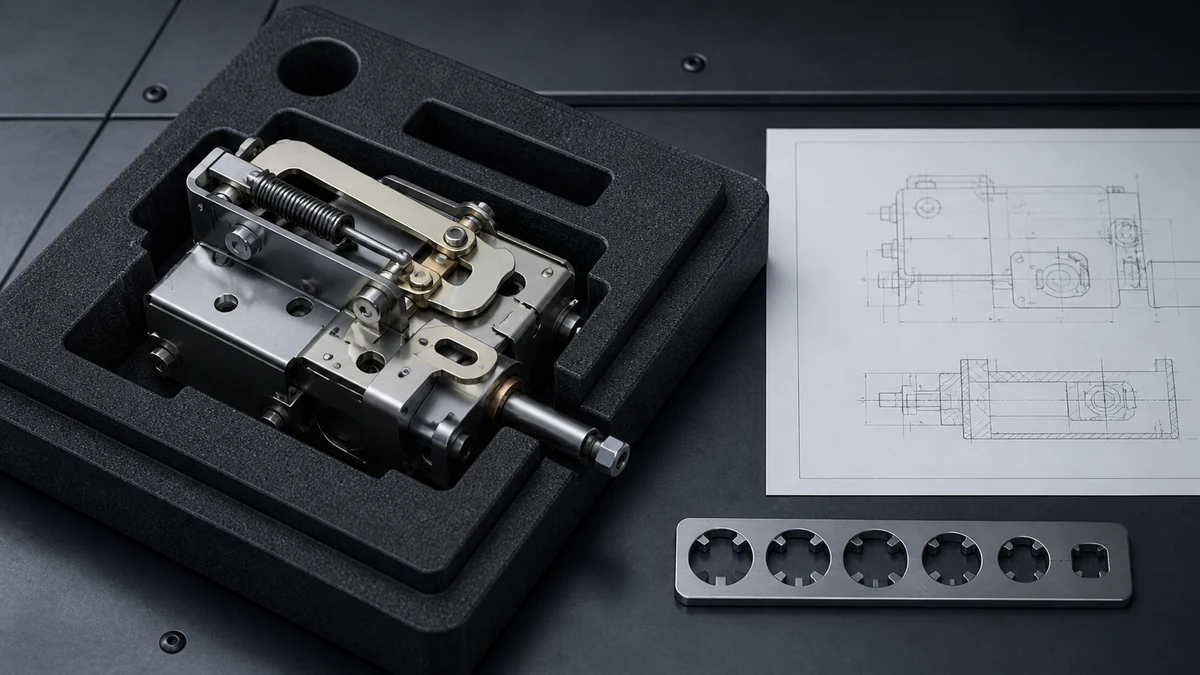
Send the request type, manufacturer, equipment model/year, part reference, ratings, quantity, destination, required date, and any drawing or photo notes. The SUVELL team will review the request.
Email: admin@suvell.com
Phone: +86 189 6871 1705
Factory: No.208 Wei 12 Rd, Yueqing Economic Development Zone, Wenzhou, Zhejiang, China
RMU Operating Mechanism Replacement: Shaft, Travel, Interlock, and Contact Data
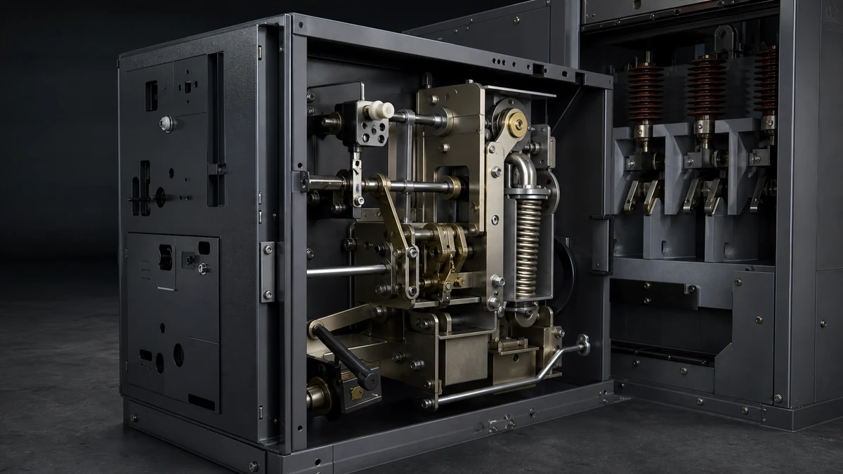
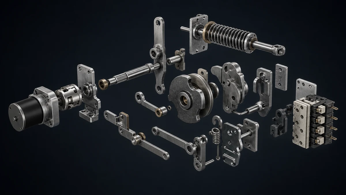
RMU operating mechanism matching depends on what the mechanism controls and how it moves, locks, and signals. Use this guide to assemble shaft, travel, interlock, auxiliary-contact, and condition evidence for a replacement RFQ without assuming interchangeability from the front plate or handle opening.
Identify whether the RMU mechanism operates a switch, circuit breaker, or fuse-switch, and record its manual, motorized, or remote control arrangement.
Document the shaft coupling, permitted travel sequence, position indication, and mechanical or electrical interlocks before comparing replacement mechanisms.
Include auxiliary-contact states, terminal markings, limit-switch functions, and failure photographs; a matching handle slot does not confirm the control logic.
An **RMU operating mechanism replacement** should be matched by function, shaft interface, travel behavior, interlocking, control arrangement, and auxiliary contact data—not by external appearance alone. For RMU Operating Mechanisms, a decision-stage RFQ should prove how the original mechanism operates inside the panel and how it interacts with manual drive, motor operation, locks, signals, and the switching device it controls.
This checklist keeps the request inside mechanism matching data only. It does not require unsupported model dimensions, current ratings, voltage ratings, or assumptions about interchangeability. If the existing mechanism is worn, corroded, incomplete, or unidentified, the safest replacement discussion starts with clear photos, unit references, wiring evidence, and documented operating positions.
Decision Checklist for Mechanism Matching
Confirm the mechanism function
Identify what the mechanism operates before comparing parts. RMU catalogues distinguish operating mechanisms for different functions, including switch mechanisms, circuit-breaker mechanisms, and fuse-switch mechanisms. These are not automatically interchangeable, even when the front-panel handle position or enclosure layout looks similar.
Record the mechanism function as one of the following, using the wording from the nameplate, manual, drawing, or customer documentation where possible:
Also record the switching position labels visible on the panel or mechanism plate, such as closed, open, earthed, charged, discharged, or tripped, only if they are actually present on the equipment. Do not infer labels from another RMU model.
Capture manual, remote, and electrical locking arrangement
A replacement request should state the control arrangement, because RMU mechanisms may be manual, remote-operated, motorized, or equipped with electrical locking functions. The replacement proposal depends on these control details as much as on the mechanical layout.
Use this checklist:
Is the mechanism manually operated only?
Is it motorized or remote controlled?
Is there an electrical lock or blocking device?
Is there a closing coil, opening coil, motor, release, or other actuator connected to the mechanism?
Are there plug connectors, terminal blocks, or hardwired leads attached?
Are manual and remote modes both present?
Is there a documented lockout, permissive, or inhibit condition?
If the original control arrangement is unknown, provide photos of the mechanism front, rear, side, auxiliary devices, terminal markings, and control wiring before selecting a replacement.
Record operating shaft access and shaft interface evidence
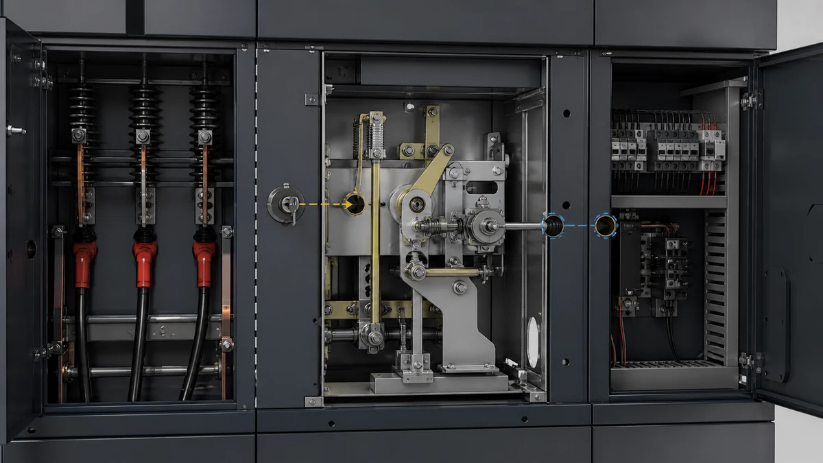
Operating-shaft access is a distinct system function in RMU documentation. The replacement mechanism must match how the handle, shaft, and internal operating parts engage.
Record evidence for:
Manual operating-shaft access point
Handle insertion orientation
Visible shaft end shape
Coupling style between handle input and mechanism
Any cover, shutter, or access interlock affecting the shaft
Whether shaft access changes between service positions
Signs of wear, distortion, looseness, corrosion, or failed return movement
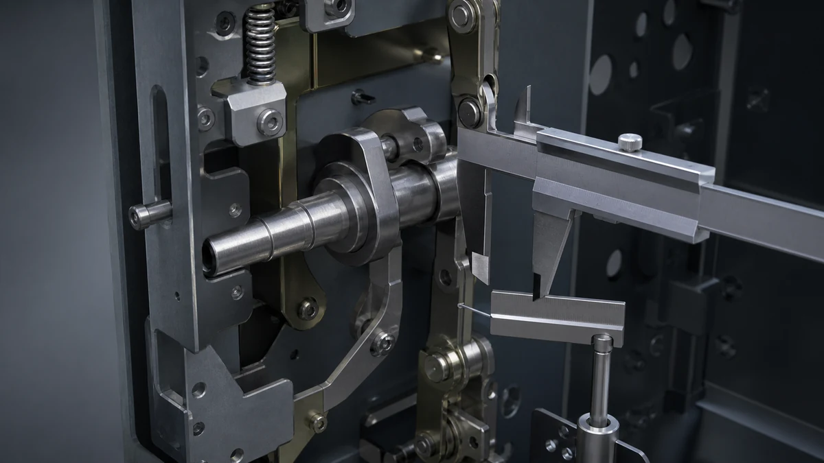
Avoid estimating dimensions unless they are measured directly from the existing part and requested by the supplier. Photos taken square-on to the shaft access area are usually more useful than a written description alone.
Document travel, sequence, and position indication
Mechanism travel is not only a matter of handle angle. It includes the sequence of operations, stored-energy state where applicable, position indication, and how the mechanism reaches each permitted state.
Document the following without forcing the mechanism if it is damaged:
Starting position shown on the indicator
Ending position after manual operation, if safe to operate
Whether operation is spring-charged, direct-drive, trip-free, or otherwise documented
Whether the mechanism has separate close, open, earth, charge, or trip actions
Whether the indicator returns positively and consistently
Whether there is abnormal resistance, incomplete travel, or delayed return
Whether movement is blocked by lock, key, cover, or interlock
If the mechanism is already failed, do not rely only on the final stuck position. Provide evidence of the unit reference and any service records showing the normal operating sequence.
Identify interlocks before judging interchangeability
Interlocks, shaft access, control wiring, and order-related coding are separate functions that can affect whether a mechanism is suitable. Matching only the visible handle slot or mounting face can miss an interlock dependency.
Record all visible and documented interlock features:
Key interlocks
Mechanical blocking plates
Padlockable devices
Door or cover interlocks
Earthing-switch interlocks
Cable-test or access interlocks
Electrical permissive contacts
Motor inhibit contacts
Position-dependent lockouts
RM6 guidance describes limit switches that inhibit motor operation during manual mechanism actions or locking actions. Therefore, manual drive, motorization, interlock condition, and limit-switch behavior should be recorded together before a replacement is evaluated.
Provide auxiliary contact and limit-switch data
Auxiliary contacts and limit switches may be used for signalling, interlocking, motor inhibition, remote indication, or control logic. Because precise control, interlocking, and signalling matching can limit component replacement without the correct documentation, contact data should be included in every serious RFQ.
Provide:
Photos of auxiliary-contact blocks and limit switches
Terminal numbers or wire markers
Contact state in each documented mechanism position, if known
Control schematic page or wiring diagram, if available
Connector type and pin/wire location evidence
Whether the contact is used for indication, motor control, locking, or protection logic
Any failed, burned, loose, or corroded contact assemblies
Do not substitute contact assumptions from a similar RMU. If the drawing is unavailable, state that the contact function is unknown and provide high-resolution photos.
Include condition and failure evidence
Maintenance guidance treats corrosion and the condition of moving operating-mechanism parts as inspection items. This means wear evidence is not cosmetic; it can help identify the correct replacement reference and prevent repeated failure.
Include photos and notes showing:
Corrosion on springs, pivots, shafts, levers, plates, or fasteners
Broken, bent, missing, or loose parts
Abnormal wear marks
Damaged bearings, pins, clips, or couplings
Failed return springs or stored-energy components
Evidence of water ingress, dust contamination, or mechanical seizure
The complete RMU unit reference and any mechanism reference plate
If the operating mechanism has already been removed, photograph the removed mechanism from all sides and also photograph the mounting area inside the RMU.
Prepare the RFQ data pack
For a decision-stage replacement request, the most useful RFQ pack is a controlled set of evidence rather than a long verbal description.
Minimum recommended data pack:
Data item
Why it matters
RMU unit reference photo
Helps connect the mechanism to the correct equipment family and order-related coding
Mechanism reference photo
May identify the exact mechanism version or function
Function description
Distinguishes switch, circuit-breaker, and fuse-switch mechanisms
Manual/remote mode evidence
Confirms whether motorization or remote control must be matched
Electrical locking evidence
Prevents omission of blocking or permissive functions
Shaft access photos
Supports interface matching
Position-indicator photos
Shows the operating sequence and state labels
Interlock photos
Identifies mechanical or electrical dependencies
Auxiliary contact and wiring photos
Supports signalling and control matching
Failure and condition photos
Shows wear, corrosion, missing parts, and inspection findings
A complete RFQ should say what is known, what is unknown, and what documentation is available. It is better to mark a control or contact function as unknown than to assume it from appearance.
Avoid unsupported matching assumptions
Do not approve an RMU operating mechanism replacement based only on:
Similar front plate appearance
Similar handle slot location
Similar enclosure layout
A partial photo of the mechanism
Verbal statement that the RMU is “the same type”
Unverified assumptions about auxiliary contacts
Missing interlock or wiring information
Unconfirmed manual versus motorized operation
The replacement mechanism must be assessed against the original function and control arrangement. Where documentation warns that precise control, interlocking, and signalling affect replacement, the RFQ should include the relevant drawings or photographic evidence before a final decision.
FAQ
What is the minimum data set for RMU operating mechanism replacement?
The minimum data set should include the RMU unit reference, mechanism reference, mechanism function, manual or remote control arrangement, shaft access photos, operating-position evidence, interlock details, auxiliary-contact or limit-switch evidence, and condition photos. This allows the supplier to evaluate the mechanism as a functional assembly rather than only as a visible part.
What is the difference between matching by appearance and matching by function?
Matching by appearance compares visible features such as handle slots, plates, and general layout. Matching by function checks what the mechanism actually operates, how it is controlled, how it interlocks, how the shaft is accessed, and how auxiliary contacts or limit switches behave. For RMU operating mechanisms, functional matching is the safer basis for replacement.
What is the role of interlock data in a replacement request?
Interlock data shows whether the mechanism is allowed, blocked, or inhibited under certain conditions. Mechanical locks, key systems, shaft-access shutters, electrical locking, and motor-inhibit limit switches can all affect replacement suitability. If these details are missing, a visually similar mechanism may still fail to match the original control and safety logic.
What is useful photographic evidence for a damaged mechanism?
Useful evidence includes the full mechanism from several angles, the shaft access point, position indicator, interlock devices, springs and moving parts, auxiliary contacts, wiring terminals, mechanism reference labels, and RMU unit reference labels. Photos of corrosion, wear, broken parts, and incomplete travel are also meaningful because maintenance guidance treats the condition of moving mechanism parts as an inspection item.
What is not enough for an RFQ?
A single front-view photo is not enough. A statement such as “same RMU mechanism” is also not enough unless it is supported by unit reference, mechanism function, control arrangement, interlock data, and contact or wiring evidence. The request should avoid unsupported dimensions, ratings, or assumptions that are not confirmed by the existing equipment or documentation.
LEO Chen
With more than 20 years of industry experience, LEO Chen has worked with major companies on switchgear, transformer components and medium-voltage equipment projects. He contributes practical guidance for engineers and sourcing teams, with a focus on clear selection criteria, application context and the information needed to prepare an informed RFQ. Connect with LEO on LinkedIn.