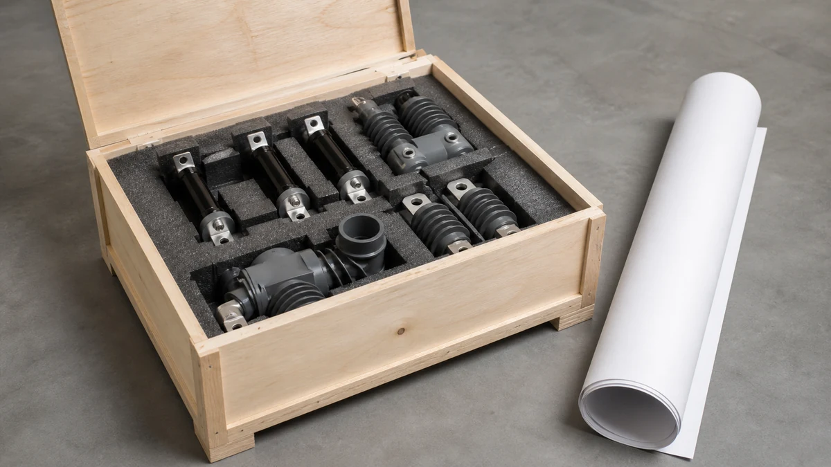
Send the request type, manufacturer, equipment model/year, part reference, ratings, quantity, destination, required date, and any drawing or photo notes. The SUVELL team will review the request.
Email: admin@suvell.com
Phone: +86 189 6871 1705
Factory: No.208 Wei 12 Rd, Yueqing Economic Development Zone, Wenzhou, Zhejiang, China
RMU Load Break Switch Inspection: Contacts, Mechanism, and Indication Checks
RMU load break switch inspection relies on external mechanism checks, configured indicators, interlocks, and service history when contacts are inside a sealed compartment. This guide defines that inspection boundary and the records needed to evaluate indication faults, mechanical problems, or abnormal gas readings.
For the sealed RMUs discussed here, routine external inspection covers mechanisms, indicators, interlocks, and enclosure condition without opening the gas compartment.
Record load-break and earthing-switch indications separately, and inspect the fitted voltage-indication system without treating it as proof of absence of voltage.
Use operation history and the unit’s documentation to assess contact concerns, record pressure or density indications, and escalate mechanism or gas-condition anomalies.
RMU load break switch maintenance inspection is a structured, visual and functional review of the switching contacts, operating mechanism, position indicators, and interlocks — performed without opening the sealed gas compartment or disturbing the arc-quenching medium. The boundary matters: everything accessible from outside the enclosure is in scope; internal gas work is not. Getting that boundary wrong, in either direction, either creates unnecessary gas handling risk or leaves real inspection gaps undetected.
What the Inspection Is — and What It Is Not
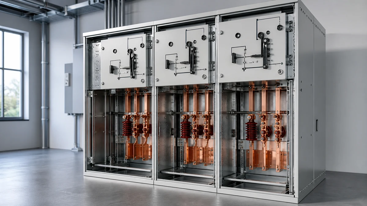
A ring main unit houses the load break switch in a sealed SF₆ or alternative-gas compartment. The switch interrupts load current through an arc-quench mechanism built into that sealed space. You cannot inspect the contacts directly, and you should not try to. What you are inspecting is everything that transfers intent and confirms state between the operator and that sealed mechanism: the operating shaft and lever, the position indicator, capacitive voltage indication probes, mechanical interlocks, and the visible mechanical condition of the enclosure.
This is not a trivial scope. Most field failures in MV switching equipment — stuck operations, indication errors, interlock bypasses — originate in the external mechanism, not inside the sealed compartment. The inspection plan described here targets that failure population directly.
The distinction also governs documentation requirements. ABB's SafeRing/SafePlus 12–24 kV installation and operating instructions treat inspection intervals and scope as product- and operating-condition-specific rather than prescribing a universal schedule. Applying a generic checklist without cross-referencing the installed unit's documentation is a compliance gap, not a conservative default.
Functional Architecture: What You Are Actually Checking
Understanding the mechanical chain makes the inspection coherent rather than a box-ticking exercise.
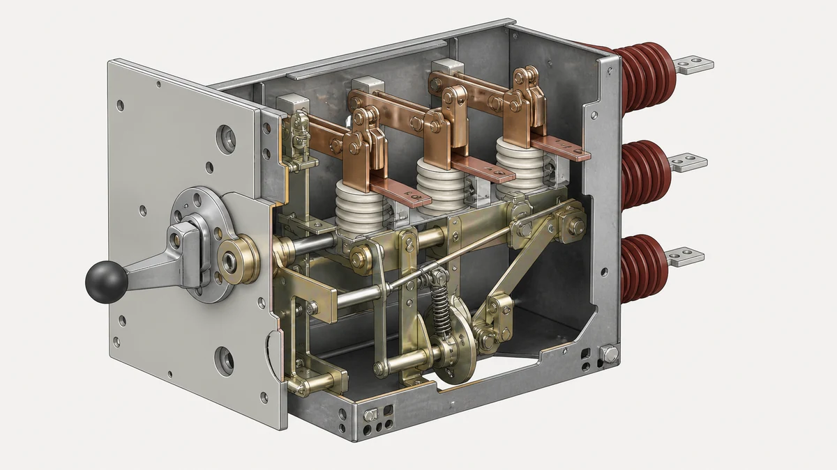
The load break switch operates through a stored-energy or manual spring mechanism connected to the switching contacts via a shaft assembly. When the operating lever completes its travel, the mechanism trips to the end position and the contacts open or close. The position indicator is mechanically driven by that same shaft — it does not sense voltage or current, it reads shaft position. This means an indication error can coexist with correct electrical switching, or correct indication can coexist with a partially operated mechanism that did not achieve full contact travel.
ABB's 36 kV SafeRing/SafePlus manual confirms that the load break switch, earthing switch, position indicator, pressure indication, and optional key interlock are distinct configured features. Their presence and correct function must be confirmed against the installed RMU's documentation rather than inferred from enclosure appearance. A unit without a key interlock from factory is not a unit with a disabled interlock — those are different configurations with different inspection requirements.
The earthing switch is a separate device with its own position indicator and its own interlock logic. Both must be checked independently; sharing a visual scan across both is a common source of missed defects.
Contact Condition: Indirect Evidence
You cannot see the contacts, but you can develop a credible indirect picture.
**Operation count and service history.** Contacts wear with each switching operation. The installed documentation will specify a rated number of load break operations; knowing where the unit sits against that rating tells you whether contact wear is a current concern or a future one. If operation records are unavailable, that gap itself is a finding.
**Transition resistance indication.** Some RMU designs provide fixed-period resistance measurement points, or a thermal survey can be conducted during energised conditions by qualified personnel. Elevated temperature at the cable termination compared with adjacent phases suggests increased resistance at the contact interface — an indirect signal that contact condition may be degrading.
**Mechanism feel and travel.** Operating force and travel distance are calibrated at commissioning. A lever that requires noticeably more force, travels further before tripping, or snaps inconsistently is reporting a change in the mechanism or contact interface. Log the subjective assessment and compare to previous records; the trend matters more than a single reading.
Position Indicator Verification
The position indicator is the primary status interface between the RMU and the operator. Getting it wrong has direct safety consequences — an earthed switch shown as open, or an open switch shown as earthed, can result in a live work incident.
ABB SafeRing/SafePlus 12–24 kV instructions explicitly identify the load-break/earthing-switch position indicator as a distinct feature requiring verification. The inspection must confirm three things independently:
**Visual check.** Indicator window clean and unobscured; indication clearly legible from the normal operating position; lamp or mechanical flag in undamaged condition.
**Agreement with switching operation.** Operate the switch through one complete open-close cycle — or verify from records that this has been done within the applicable inspection interval — and confirm the indicator changes state correctly at both ends of travel. An indicator that changes partway through lever travel, or not at all, is a failure.
**Agreement with other indications.** Where capacitive voltage indication (CVI) probes are fitted, the CVI reading should be consistent with the switch position shown. An open switch on a live feeder should give a CVI indication; a closed switch to an isolated cable should not. Discrepancy between CVI and switch position is either a CVI fault or an indication fault — both warrant investigation before the unit is returned to service.
Capacitive Voltage Indication
CVI probes are fitted to allow safe confirmation of conductor state without contact. ABB SafeRing/SafePlus 12–24 kV installation and operating instructions include capacitive voltage indication as a distinct feature whose function must be checked.
The inspection covers probe integrity (no visible cracking, contamination, or mechanical damage), indicator lamp or LED function (a test facility is typically provided), and agreement between CVI state and known system conditions where verifiable. CVI does not replace an authorised proving-dead procedure — it is a first-indication device and inspection confirms it is operational, not that it is sufficient for working on.
Probes are phase-specific. A full inspection checks all three phases, not just one.
Operating Mechanism and Interlock Checks
The mechanism is the component most exposed to environmental degradation. It lives outside the sealed gas compartment, sees temperature cycling, condensation, and mechanical wear through every operation.
**Visible mechanical condition.** Check the operating lever for deformation, corrosion, and secure attachment. The shaft gland or seal where the operating shaft enters the sealed compartment deserves particular attention — any visible corrosion at the interface suggests potential for moisture ingress toward the gas boundary.
**Snap-action and end-stop confirmation.** The load break switch is designed to trip to the open or closed position with sufficient speed to interrupt load current. An operating mechanism that allows slow or partial operation defeats the arc-quench design. The lever should snap through at the rated point in the travel and seat firmly at the end stop.
**Key interlock function.** ABB's 36 kV SafeRing/SafePlus manual lists the optional key interlock as a distinct configured feature. Where fitted, the inspection must verify that the interlock prevents out-of-sequence operation — specifically, that the earthing switch cannot be closed onto a live circuit and that the load break switch cannot be opened with the earthing switch closed, per the configured logic. Operate the interlock sequence per the unit's scheme to verify. A seized, corroded, or modified key barrel is a finding regardless of whether a prohibited sequence has been attempted.
**Mechanical earthing switch interlock.** Independent of any key scheme, the mechanical interlock between the load break switch and earthing switch must be checked. The interlock is the physical barrier preventing simultaneous closure. Confirm it engages correctly in both switch positions.
Enclosure and Gas Pressure Indication
The sealed gas compartment is not opened during inspection, but its external condition is within scope.
**Gas pressure or density indicator.** ABB's 36 kV SafeRing/SafePlus manual includes pressure indication as a distinct configured feature. Where fitted, the indicator should read within the manufacturer's specified range for the ambient temperature at time of inspection. Some designs use a density monitor that temperature-compensates automatically; others show gauge pressure requiring a temperature correction. Know which type is installed before interpreting the reading.
A low-pressure reading does not mandate immediate gas work — it mandates escalation to a qualified gas engineer following the unit's service documentation. The inspection role is to detect and report, not to remediate gas faults.
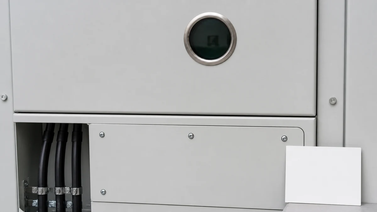
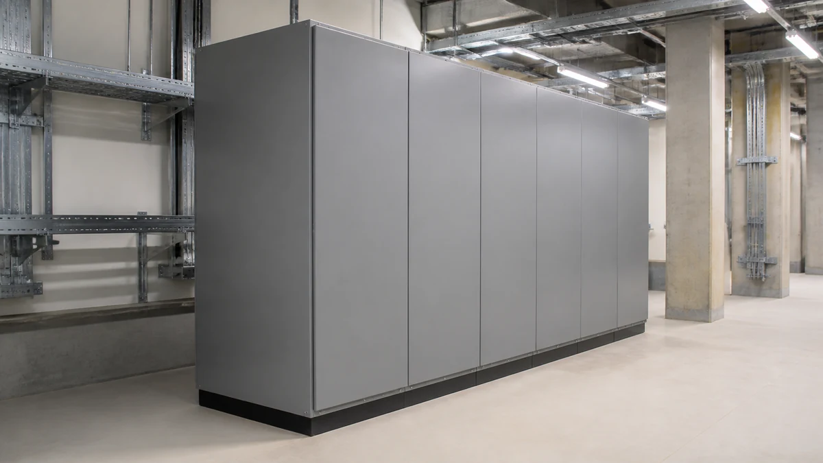
**Enclosure condition.** Inspect for corrosion, paint loss, seal degradation at cable entry points, and any signs of moisture ingress at cable boxes. Note any deformation that might suggest mechanical impact. These findings do not directly affect the switching function but affect the long-term integrity of the sealed compartment.
Inspection Intervals and Documentation Requirements
ABB SafeRing/SafePlus instructions across both the 12–24 kV and 36 kV product families treat maintenance intervals as product- and operating-condition-specific rather than prescribing a universal schedule. The relevant variables include installation environment (indoor, outdoor, coastal, industrial), operating duty (number and frequency of switching operations), and any grid operator or asset owner requirements that may be more stringent than the manufacturer's baseline.
What this means practically: a single inspection interval applied across a mixed RMU fleet without reference to each unit's installed documentation is not compliant with the manufacturer's intent. Inspection planning should start from the unit's own manual, cross-referenced with the operating environment classification and the site's maintenance management system.
Documentation outputs from each inspection should record: unit ID and feeder, date and ambient conditions, gas pressure reading with temperature, position indicator check result, CVI check result, interlock sequence check result, mechanism operation assessment, any defects found with severity classification, and the name of the qualified person conducting the inspection. A record that says only "satisfactory" without supporting observations has no diagnostic value when the next inspection compares to it.
Common Defects and Their Significance
Understanding what defects look like in this equipment helps an inspection team calibrate severity correctly rather than treating every finding as either trivial or critical.
**Sluggish mechanism.** Usually caused by lubricant degradation or corrosion in the operating shaft bearings. Significance depends on degree — marginal sluggishness may be addressable through approved external lubrication; a mechanism that cannot reliably trip to the end position is a service-affecting fault requiring escalation.
**Indication discrepancy.** A mismatch between indicator state and system conditions is always a safety concern. It does not automatically mean the switch is in the wrong position — it may mean the indicator mechanism has failed while the switch itself operated correctly. Either condition requires investigation and resolution before the unit is operated again.
**Corroded or seized key barrel.** A key interlock that cannot be operated defeats its safety function. Depending on the interlock scheme, a seized barrel may prevent authorised switching operations as well as prohibited ones. Both outcomes are service-affecting.
**Low gas pressure.** In the absence of any switching anomaly, low pressure may be a slow leak detectable only through periodic monitoring. The immediate action is to compare the current reading against previous records to assess rate of change, then escalate to the manufacturer's service procedure.
**CVI lamp failure.** A failed lamp is not a gas fault or a switching fault, but it removes a first-indication tool from service. Replacement should follow the unit's service documentation.
Pre-RFQ and Replacement Decision Data
If inspection findings support a replacement or spares procurement decision, the data set needed before an RFQ is specific.
**From the nameplate:** unit type designation, voltage rating, rated normal current, rated short-circuit making current, year of manufacture, and serial number. For ABB SafeRing/SafePlus equipment this will identify which product generation and configuration is installed — the 12–24 kV and 36 kV variants have different mechanical designs and the replacement components are not interchangeable.
**From the documentation:** configuration of optional features — whether a key interlock is fitted, which CVI system is installed, whether pressure indication is analogue gauge or electronic density monitor. Replacing a unit without replicating its interlock scheme creates a scheme mismatch that may not be immediately apparent.
**From the inspection record:** the specific defect driving the replacement decision. A worn mechanism that has reached its rated operation count is a different procurement scope from an indication system failure or a low-pressure event — the first may require a full unit replacement, the second may be addressable with a component-level repair kit where the manufacturer supports it.
**Operating environment classification:** indoor versus outdoor, pollution degree, altitude if above 1000 m. These affect which replacement unit variant is applicable.
Suppliers offering MV switching device components should be able to confirm compatibility with the installed unit type by model reference before supply. A quotation that does not reference the installed unit's model designation is not a verified compatible supply.
—
FAQ
What is the difference between a load break switch and a circuit breaker in an RMU?
A load break switch is rated to make and break load current — the normal current flowing in the circuit — but is not designed to interrupt fault current. A circuit breaker can interrupt fault current, typically of an order of magnitude higher than load current. In a standard ring main unit, the load break switch handles normal switching operations; fault protection is provided by a separate fuse or circuit breaker in the protection panel. This distinction matters for inspection because a load break switch that has been called on to interrupt abnormal currents may show accelerated contact wear not reflected in its operation count.
What is capacitive voltage indication and why does it need to be checked?
Capacitive voltage indication uses a small capacitor probe installed on the busbar or cable conductor to couple a low-level signal to an indicator when the conductor is energised. It gives the operator a first-indication of conductor state without making contact with live parts. It requires inspection because a failed lamp or degraded probe gives a false "dead" reading — the absence of indication does not confirm absence of voltage. Inspection verifies that the CVI system is operational, which is a prerequisite for it to serve as a useful first-indication tool in safe working procedure.
What is a mechanical interlock between the load break switch and earthing switch?
The mechanical interlock is a physical linkage or blocking feature designed to prevent both the load break switch and the earthing switch from being closed simultaneously. Closing the earthing switch onto a live busbar would create a bolted fault; the interlock is the last-line-of-defence barrier against this. In the RMU designs covered by ABB SafeRing/SafePlus documentation, the interlock is a configured feature whose function must be verified independently from any key interlock scheme that may also be present.
What is the significance of operating condition classification for inspection intervals?
ABB SafeRing/SafePlus maintenance documentation does not prescribe a universal inspection interval because the correct interval depends on the installed environment and switching duty. A unit in a clean indoor substation on a stable network has a different wear profile from one in an outdoor coastal enclosure on a network with frequent fault-induced switching. Applying a conservative interval across all units regardless of condition may be workable as a conservative policy, but the manufacturer's framework is that each unit's interval should be derived from its own conditions. The significance for an inspection programme is that the documented basis for the chosen interval should be traceable to the installed unit's documentation, not to a fleet-average assumption.
What is the role of gas pressure indication in an external inspection?
Gas pressure or density indication is the only window the inspection team has into the condition of the sealed arc-quench environment without opening the compartment. A reading within the specified range confirms that the sealed compartment has maintained its integrity since the last check. A reading outside the range does not define the cause — it could reflect a slow leak, a temperature compensation error in a gauge-type indicator, or a previous unreported gas loss event. The inspection role is to read, record, and escalate; gas remediation work is out of scope for a standard inspection and requires qualified gas engineers following the manufacturer's service procedure.
LEO Chen
With more than 20 years of industry experience, LEO Chen has worked with major companies on switchgear, transformer components and medium-voltage equipment projects. He contributes practical guidance for engineers and sourcing teams, with a focus on clear selection criteria, application context and the information needed to prepare an informed RFQ. Connect with LEO on LinkedIn.