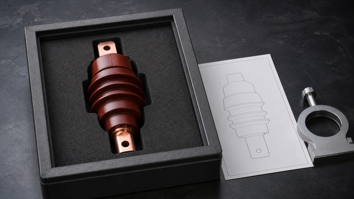
Send the request type, manufacturer, equipment model/year, part reference, ratings, quantity, destination, required date, and any drawing or photo notes. The SUVELL team will review the request.
Email: admin@suvell.com
Phone: +86 189 6871 1705
Factory: No.208 Wei 12 Rd, Yueqing Economic Development Zone, Wenzhou, Zhejiang, China
How to Match an Epoxy Resin Bushing Replacement to an Existing RMU Interface
Replacing an RMU epoxy resin bushing requires matching its electrical connection and mechanical interface together. This guide identifies the contact, mounting, cable orientation, and drawing evidence needed for a supplier review, including how to record missing data before requesting a replacement quote.
Match the RMU bushing’s electrical duty, contact position, and mating interface; a similar molded profile or legacy part number does not establish equivalence.
Compare the mounting bore, seating face, retention method, and seals alongside cable orientation and available termination clearance.
Attach labeled photographs, reference dimensions, and the RMU drawing to the RFQ, with missing ratings and interface details marked for confirmation.
Scope and review method
This is an RFQ-preparation guide for industrial procurement and maintenance teams. It helps collect the information a supplier or product owner needs to review a proposed replacement; it does not certify a substitute, approve an installation, or replace the current RMU drawing, OEM manual, project procedure, or qualified engineering review.
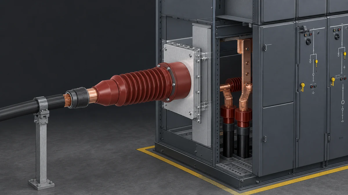
An **epoxy resin bushing replacement** for an RMU should be matched as an interface component, not selected only by appearance, a legacy reference, or a broad voltage class. In switchgear, the bushing’s job is both insulation and connection; in some medium-voltage switchgear arrangements, epoxy-resin insulating bushings also contain the contacts that connect switching equipment to the busbar compartment through the disconnector path. That means the replacement decision must confirm electrical duty, interface geometry, contact arrangement, mounting retention, and cable-side compatibility before purchase.
Use this checklist when you already have an installed RMU, an existing bushing, or a defined panel interface and need to confirm whether a replacement bushing is equivalent.
Confirm the replacement is being matched to the actual RMU interface
Start with the interface, not the part photo. A bushing that looks similar may still fail to match the panel because switchgear bushings can vary by size, shape, contact design, and mounting options. A legacy part number or a single image is useful evidence, but it is not enough to prove replacement equivalence.
Checklist:
Identify the RMU make, model, panel type, and function.
Record the original bushing reference exactly as marked, if visible.
Photograph the installed bushing from the cable side, tank or panel side, and mounting face.
Confirm whether the bushing is part of a cable connection, busbar interface, circuit-breaker connection, disconnector path, or another switchgear interface.
Separate cosmetic similarity from interface compatibility.
Ask for dimensional or standard-interface confirmation before accepting a substitute.
Decision rule: if the bushing participates in both insulation and electrical connection, the replacement must be checked as a mechanical-electrical interface assembly, not as a generic molded epoxy component.
Verify the electrical duty inputs before comparing dimensions
For RMU connection-interface definition, current, short-time withstand duty, connection type, output position, system voltage, and cable construction are all relevant inputs. These should be collected before choosing an epoxy resin bushing replacement because the same general bushing family may include different interface variants.
Checklist:
Rated current required by the existing interface.
Short-time withstand duty required by the panel or system.
System voltage of the installed RMU.
Connection type used at the bushing interface.
Output position and orientation.
Cable construction connected to the interface.
Whether the bushing is used with a separable connector, busbar connection, or internal contact path.
Any project-specific interface standard stated in the original documents.
Do not invent missing ratings. If the nameplate, drawing, or service manual does not confirm a value, treat it as an open item and request confirmation from the switchgear owner, OEM documentation, or a qualified supplier.
Check the applicable interface standard, not only the molded profile
Connection interfaces are often defined by an applicable interface standard, including the interface profile, contact arrangement, and dimensions. This is important because molded epoxy surfaces can appear compatible while the contact depth, reference plane, sealing face, or dimensional standard differs.
Checklist:
Identify the applicable interface standard named in the original documentation.
Confirm the interface profile against that standard.
Check contact type, contact position, and contact depth.
Confirm dimensional reference points, not only overall length.
Compare the mating connector or busbar-side requirement.
Verify that the replacement supplier can confirm equivalence to the same interface requirement.
Reject “visually similar” substitutions unless the standard interface and dimensions are confirmed.
A correct replacement should preserve the defined interface relationship between the RMU, contact system, and connected cable or busbar component.
Match the contact function and current path
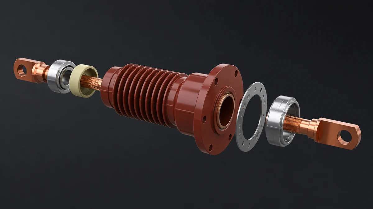
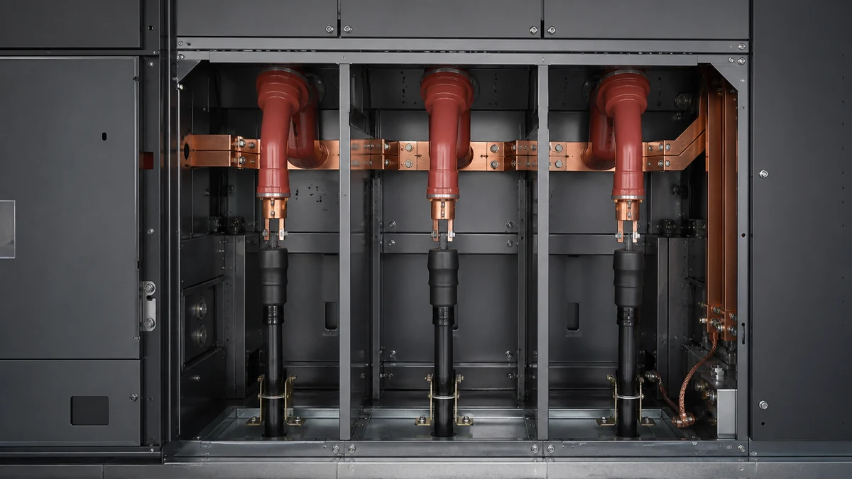
In medium-voltage switchgear, epoxy-resin insulating bushings may contain the contacts that connect the circuit-breaker to the busbar compartment through a three-position disconnector. Even when the exact RMU design differs, the lesson is the same: the bushing may be part of the current path, not only an insulating sleeve.
Checklist:
Confirm whether the original bushing contains a fixed contact.
Identify the mating moving contact, cable connector, busbar contact, or disconnector interface.
Check contact material, contact geometry, and connection arrangement only from confirmed documentation or samples.
Confirm whether the bushing must align with an internal disconnector, breaker, busbar, or cable termination.
Inspect the original for signs of contact overheating, tracking, cracking, partial discharge marks, or mechanical stress.
Do not reuse a contact assumption from another panel type unless the interface is confirmed.
If the replacement bushing does not reproduce the contact function and alignment, it may fit mechanically but fail electrically.
Confirm mounting-face, bore-hole, and retention details
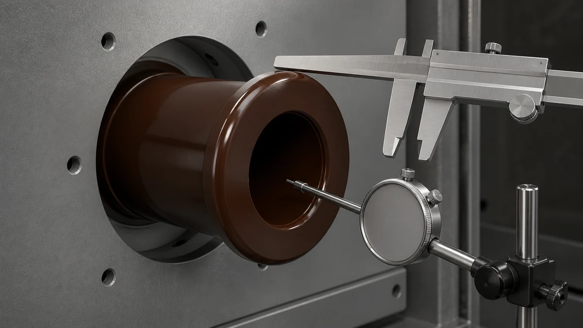
Installation guidance for switchgear busbar bushings describes mounting through a bore-hole with a retaining ring, making mechanical retention part of the assembly. Therefore, mounting-face geometry and retention design belong in every replacement review.
Checklist:
Measure the panel or compartment bore-hole.
Confirm the mounting face shape and seating surface.
Check whether a retaining ring, flange, clamp, fastener, or other retention feature is used.
Confirm the retaining-ring groove or equivalent retention geometry.
Check insertion direction and service access.
Confirm gasket, seal, or compression-interface requirements if present.
Verify that the installed bushing cannot shift under operating, thermal, or short-time mechanical forces.
Compare the replacement’s mounting arrangement to the original, not just its external profile.
A replacement that has the right electrical interface but the wrong retention method should not be treated as equivalent.
Compare orientation, output position, and cable construction
RMU connection interfaces depend not only on ratings but also on connection type, output position, and cable construction. These details affect whether the replacement will mate correctly with the existing cable termination and enclosure geometry.
Checklist:
Confirm the bushing output direction.
Check whether the cable exits horizontally, vertically, front-facing, rear-facing, or in another defined position.
Confirm the cable construction used with the existing connector system.
Verify clearances around the termination.
Confirm whether the connector boot, stress-control component, or cable termination can be installed without interference.
Check whether the original installation has phase spacing, compartment depth, or access constraints that affect the bushing choice.
Confirm whether all three phases use identical bushings or phase-specific variants.
Do not assume that a bushing suitable for one RMU panel position is automatically suitable for another output position or cable arrangement.
Inspect the removed bushing and record replacement evidence
When the existing bushing is available, it can provide valuable evidence. However, the inspection should support documented matching, not replace it.
Checklist:
Record all molded markings and labels.
Photograph the bushing with a scale from multiple angles.
Measure critical dimensions from defined reference planes.
Note contact condition and position.
Check for cracks, carbonization, erosion, deformation, or discoloration.
Record mounting hardware, retaining rings, seals, and washers.
Keep the original part until the replacement is received and verified.
Compare the replacement against both the removed part and the RMU interface documentation.
If the original failed, identify whether the failure was caused by age, installation damage, connector mismatch, overheating, contamination, or mechanical stress. Replacing the bushing without addressing the cause may repeat the failure.
Use a decision checklist before approving purchase
Before releasing the order, confirm that the supplier’s replacement proposal addresses the actual interface and not only the product category.
Approval checklist:
RMU model and panel function confirmed.
Original bushing reference recorded, if available.
System voltage confirmed from reliable documentation.
Rated current confirmed.
Short-time withstand duty confirmed.
Connection type confirmed.
Output position confirmed.
Cable construction confirmed.
Applicable interface standard confirmed, if specified.
Interface profile, contacts, and dimensions confirmed.
Mounting bore-hole and retaining method confirmed.
Mounting face and retention hardware confirmed.
Contact function and current path confirmed.
Quantity and phase arrangement confirmed.
Installation constraints reviewed.
Supplier has confirmed replacement equivalence for the existing interface.
Purchase only when the replacement is matched across electrical duty, interface standard, contact arrangement, and mechanical retention.
Build a one-page interface record for the RFQ
Keep the replacement review in one controlled record so that a drawing, photograph, and supplier proposal can be compared against the same project basis. Mark every missing item as “to be confirmed” instead of filling it with a value taken from a similar panel.
Record item
Capture from
Why it matters for the review
RMU make, model, panel function, and serial or asset reference
Nameplate, panel drawing, asset register
Identifies the equipment context and the interface duty.
Original bushing marking and photographs
Removed part and installed position
Supports identification but does not prove equivalence alone.
Interface profile, contacts, and reference dimensions
Approved drawing, OEM document, measured defined planes
Establishes the actual mating relationship.
Current duty, system voltage, and short-time duty
Current project documentation
Prevents a mechanical-only comparison.
Mounting face, bore-hole, retention, seals, and orientation
Panel inspection and drawing
Confirms that the part can be retained and installed as designed.
Cable or busbar connection details and available clearance
Cable schedule, interface drawing, site photographs
Checks that the connected assembly can be completed without interference.
Supplier proposal, revision, and confirmation questions
Quotation review
Creates a traceable record of what has and has not been confirmed.
Use this record as the attachment set for the RFQ and retain the final approved drawing or supplier confirmation with the asset documentation.
FAQ
What is an epoxy resin bushing replacement?
An epoxy resin bushing replacement is a substitute insulating and connecting component used in switchgear when the original bushing is damaged, aged, obsolete, or otherwise unsuitable for service. For RMU applications, it should be matched to the existing interface, including electrical duty, contact arrangement, connection type, output position, cable construction, and mounting retention.
What is the most important check before ordering a replacement?
The most important check is interface equivalence. Confirm that the replacement matches the applicable interface profile, contacts, dimensions, electrical duty, and mechanical mounting arrangement. A photo or old part number alone may help identification, but it does not prove that the replacement will fit and function correctly.
What is the role of the contact inside a switchgear bushing?
In some switchgear designs, the epoxy-resin insulating bushing contains contacts that form part of the connection between switching equipment and the busbar compartment through a disconnector path. Because of this, the replacement must be checked for contact position, mating arrangement, and current-path function, not only insulation shape.
What is included in the mechanical matching review?
Mechanical matching should include the bore-hole, mounting face, retaining ring or other retention method, seating surface, insertion direction, seals if used, and available installation space. Mechanical retention is part of the bushing assembly, so the replacement must be secured in the same functional manner as the original design requires.
What is not enough evidence for replacement equivalence?
A legacy part number, a catalog image, or a similar molded shape is not enough by itself. Switchgear bushings can be customized by size, shape, contact design, and mounting options. Replacement equivalence should be based on confirmed RMU interface data, applicable interface standard, electrical duty, cable-side requirements, and mounting details.
LEO Chen
With more than 20 years of industry experience, LEO Chen has worked with major companies on switchgear, transformer components and medium-voltage equipment projects. He contributes practical guidance for engineers and sourcing teams, with a focus on clear selection criteria, application context and the information needed to prepare an informed RFQ. Connect with LEO on LinkedIn.