Send the request type, manufacturer, equipment model/year, part reference, ratings, quantity, destination, required date, and any drawing or photo notes. The SUVELL team will review the request.
Email: admin@suvell.com
Phone: +86 189 6871 1705
Factory: No.208 Wei 12 Rd, Yueqing Economic Development Zone, Wenzhou, Zhejiang, China
Epoxy Bushing vs Stand-Off Insulator: Different Roles Inside MV Switchgear
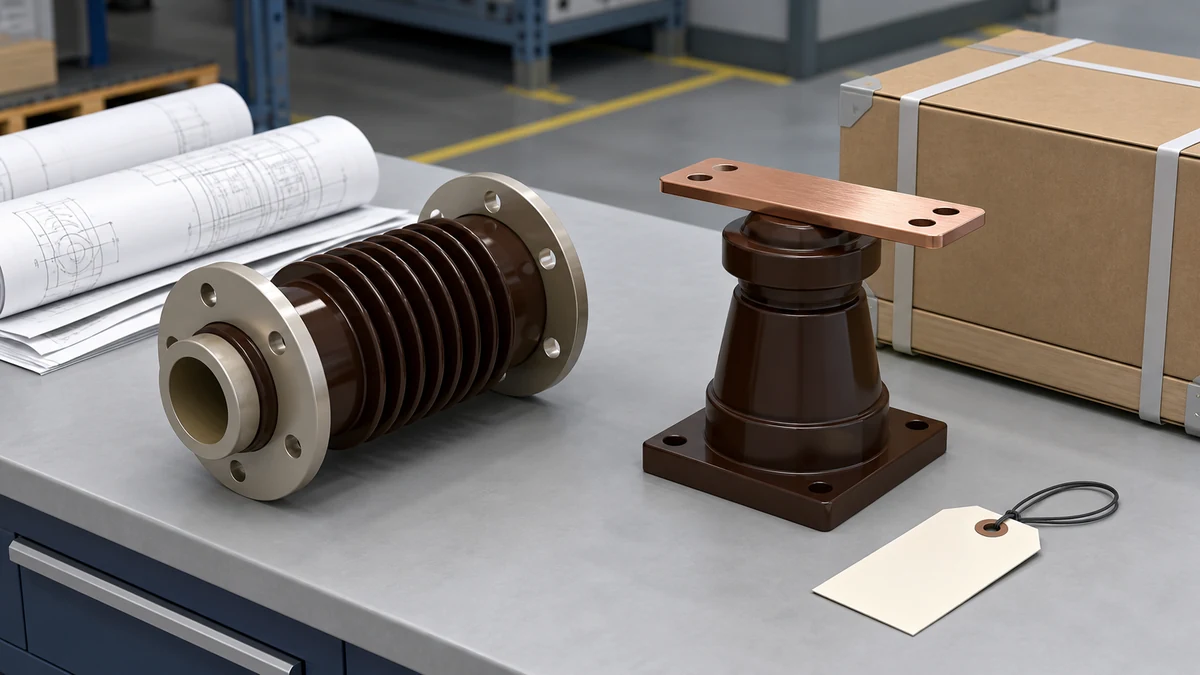
Epoxy bushings and stand-off insulators occupy different positions in the switchgear insulation system. One carries a conductor through a barrier; the other supports it at a defined distance. Learn which dimensions, mechanical loads, and drawing references distinguish their replacement and inspection requirements.
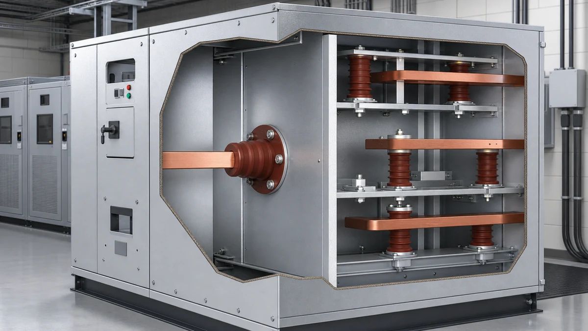
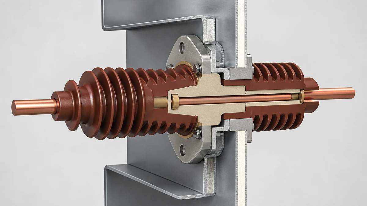
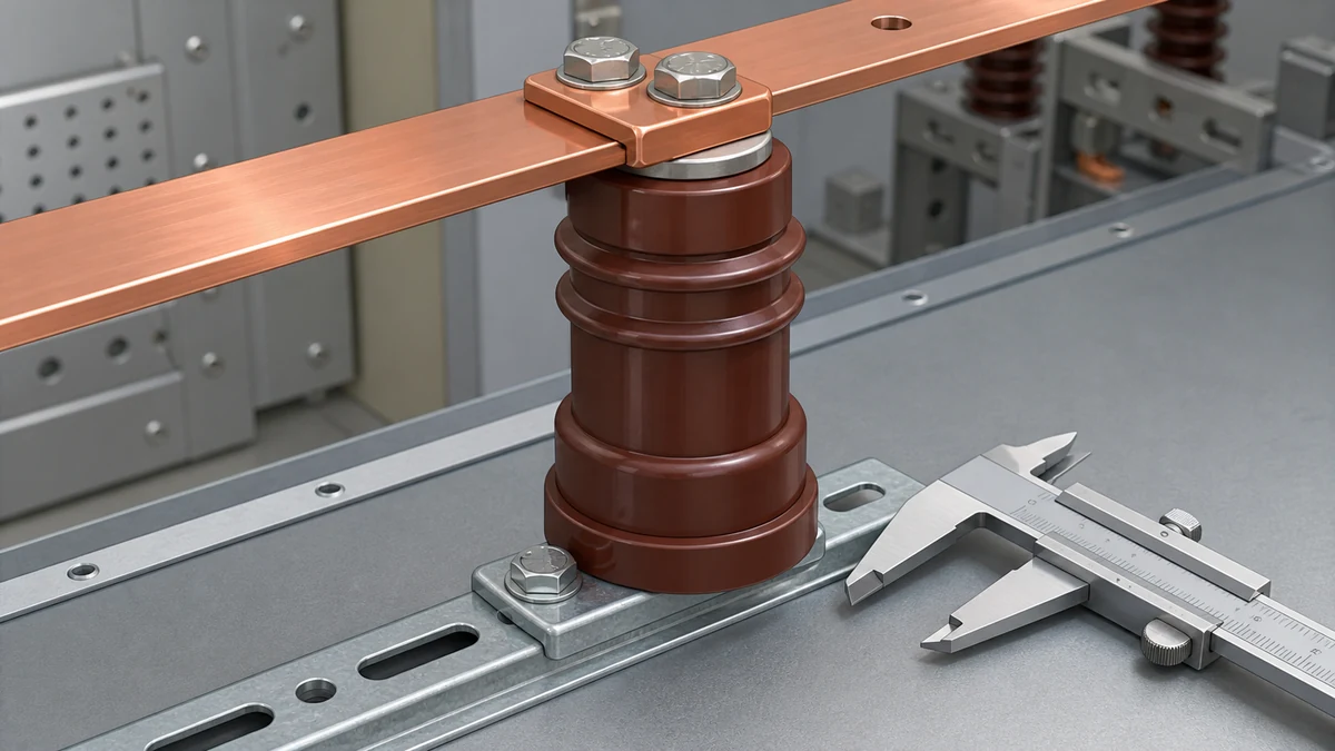
An epoxy bushing provides an insulated conductor passage through a barrier; a stand-off insulator supports a conductor away from grounded surfaces.
Bushing replacement checks include the conductor bore, flange, installed length, and creepage; stand-off checks include mounting threads, height, and support loads.
Use the cubicle drawing and identified insulation material to guide replacement and inspection, since matching voltage class does not confirm either component’s fit.
Medium-voltage switchgear cabinets contain dozens of insulating components, and the terminology around them creates real confusion at the procurement and maintenance stage. Two components that get conflated regularly are the epoxy bushing and the stand-off insulator. Both are made from dielectric materials, both operate inside the same enclosure, and both appear on drawings labeled simply as "insulator" in older documentation. But they solve different problems, live at different interfaces, and fail in ways that call for different inspection strategies.
Understanding the distinction matters most when a unit is being prepared for overhaul, when a replacement component arrives with subtly different geometry, or when a site engineer is trying to decide whether an observed crack is a bushing problem or a stand-off problem. The epoxy bushing vs insulator question is not academic — getting it wrong leads to ordering the wrong part, applying the wrong torque sequence, or leaving a bus bar inadequately supported after reassembly.
How does an epoxy bushing define the cable-to-switchgear interface?
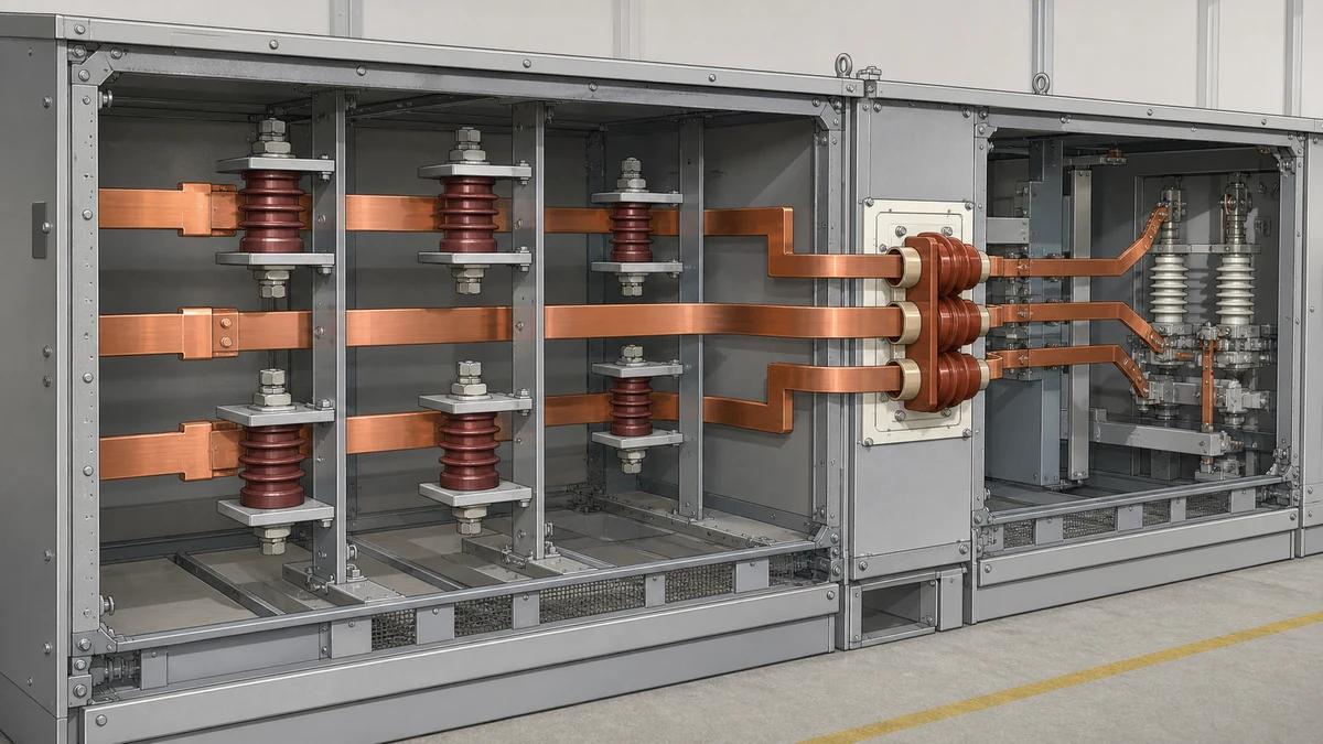
An epoxy bushing sits at the point where a conductor transitions from one compartment to another, or from outside the enclosure to inside it. Its primary job is to provide a sealed, rated passage for that conductor while maintaining the dielectric barrier between the conductor and the grounded metalwork surrounding it.
ABB's technical work on switchgear bushing materials identifies epoxy, glass polyester, and porcelain as the three materials in common use for this function. Epoxy became dominant in indoor medium-voltage equipment because cast resin tolerates the mechanical stresses of cable pulling and termination work far better than porcelain, and its surface tracking resistance in moderate-humidity environments is more predictable than glass polyester under contamination. The material description, as ABB notes, does not by itself define the replacement interface — the installed geometry, the flange pattern, the creepage distance, and the conductor size rating all carry equal weight when selecting a replacement.
What distinguishes a bushing from other insulating components is that it is load-bearing in two senses simultaneously: it carries the electrical stress of the conductor passing through it, and it carries the mechanical load of whatever is terminated on its exposed end — a cable lug assembly, a surge arrester, or a switchgear bus connection. This dual load path means that cracks in a bushing must be evaluated against both the dielectric and the mechanical specification of the original component, not just one or the other.
In Schneider Electric's Masterclad documentation, cable pass-through insulators appear as a distinct installation context, separate from bus support components. The installation procedure for each is governed by the specific equipment drawing and the relevant arrangement — a reminder that even within one manufacturer's product family, bushing configurations are not interchangeable between cubicle types without verifying the drawing package.
What does a stand-off insulator actually support?
A stand-off insulator does not carry a conductor through itself. Instead, it holds a conductor — typically a bus bar section — at a fixed distance from a grounded surface: the cabinet floor, a side panel, a horizontal partition. Its electrical job is to maintain that clearance and creepage distance under operating voltage; its mechanical job is to carry the static weight of the bus bar and absorb the short-circuit impulse forces that act on that bar during a fault event.
Schneider's Masterclad installation guidance treats stand-off bus supports as a separate installation context from cable pass-through components, and that separation is functionally significant. The stand-off insulator sees a compressive load along its axis under normal conditions and a lateral impulse during a fault. The bushing, by contrast, sees bending and torsion at its flange and conductor interfaces. Designing for one load case does not automatically produce a component that handles the other.
Stand-off insulators in metal-clad switchgear are often stacked or bracketed in groups that define the bus arrangement geometry. Replacing a single unit without verifying the stack height, the thread engagement at both mounting faces, and the phase-to-phase clearance at the new installed length can shift the bus geometry enough to reduce creepage distances on adjacent phases — a result that does not show up on a visual inspection until tracking begins.
Material differences and what they mean for service life
Epoxy resin cast components dominate both bushing and stand-off insulator applications in modern indoor switchgear, but the formulation requirements differ. Bushings typically need higher tensile and flexural strength to handle the cable termination loads, while stand-offs for bus support are formulated more for compressive strength and dimensional stability under sustained load and thermal cycling.
ABB's comparison of switchgear bushing materials covers the three material families — epoxy, glass polyester, and porcelain — in the context of bushings specifically. Glass polyester is less common in new equipment but appears in legacy installations from certain manufacturers. Porcelain stand-offs appear in older outdoor and indoor switchgear and are still found in installations that have not undergone a full insulation overhaul. When a repair involves mixing material generations, the dimensional tolerance of a new epoxy component against an old porcelain mounting surface needs to be verified against the drawing rather than assumed.
Tracking, chalking, and surface degradation present differently on epoxy versus glass polyester versus porcelain surfaces. An epoxy stand-off that has begun to track will show a carbonized path between electrodes; a porcelain component under the same conditions may show a cleaner surface because porcelain does not carbonize in the same way. Maintenance inspection procedures written for one material family may not reliably catch degradation modes in the other.
The practical implication for mixed-vintage equipment is that the material identification step needs to come before the inspection protocol step — not after. If the installed material is unknown, the safe assumption is to follow the most conservative inspection interval and surface resistance test procedure until material identity can be confirmed from the manufacturer's documentation.
Replacement and interface verification in practice
Both component types have interface parameters that must be verified before a replacement unit is fitted. For a bushing, the critical parameters are the conductor bore diameter and tolerance, the flange bolt circle and thread specification, the overall installed length relative to the panel aperture, and the creepage distance of the replacement unit compared to the original. For a stand-off insulator, the critical parameters are the mounting thread specification at both ends, the installed height under compression, and the mechanical strength rating relative to the bus bar weight and the prospective fault current at that installation point.
A component that arrives with matching voltage class and similar appearance can still be wrong if any of these parameters differ from the original. The bushing or stand-off insulator is not a commodity item that can be selected on voltage class alone — it is a precisely dimensioned piece of the overall insulation coordination scheme.
The documentation trail matters here. Schneider Electric's Masterclad installation guidance ties each component to its equipment procedure and the relevant arrangement drawing. That drawing-specific approach reflects the reality that even within a product family, panel variants exist that require different bushing or stand-off configurations. Before a replacement is ordered, the specific cubicle drawing — not just the product family reference — should be confirmed.
Where original drawings are unavailable, the safest route is dimensional measurement of the existing component, cross-referenced against the manufacturer's current component catalog and supplemented by a direct inquiry to the manufacturer's technical support channel. Assuming dimensional equivalence between a catalog part and an installed part without measurement is a common source of incorrect replacements.
Failure modes: how each component gives warning
Bushings and stand-off insulators tend to fail differently, and those differences provide maintenance-relevant signals if the inspection procedure is set up to capture them.
An epoxy bushing under cable termination stress will often develop hairline cracks at the flange root or at the point where the conductor exits the resin body. These cracks are mechanically driven by the differential thermal expansion between the conductor and the cast resin, and by repeated cable pulling and re-termination events. A cracked bushing may pass a power-frequency withstand test even after visible cracking has begun, because the crack geometry does not always create a low-resistance path. Partial discharge measurement is a more sensitive indicator and is worth including in any overhaul inspection where bushing age or termination history is uncertain.
Stand-off insulator failure is more often compressive or impact-related. A stand-off that has been overtorqued at installation, or that absorbed a high-magnitude fault current event, may show no external crack but will have internal stress fractures that reduce its mechanical strength to below the rated value. Routine visual inspection alone will not catch this. Torque verification on the mounting hardware and, where access permits, an ultrasonic test of the insulator body give a more complete picture.
Both components are also subject to contamination-driven surface tracking in environments where airborne particulates or condensation can deposit on insulating surfaces. Stand-offs in the bus compartment of a metal-clad unit are partially protected by compartment barriers, but bushings that penetrate those barriers are exposed to conditions on both sides.
FAQ
What is the key functional difference between an epoxy bushing and a stand-off insulator?
An epoxy bushing provides a rated passage for a conductor through a barrier — it carries the conductor and seals the aperture. A stand-off insulator holds a conductor at a fixed distance from a grounded surface without the conductor passing through it. The bushing manages a transition point; the stand-off manages a support point. These are different mechanical and electrical roles even though both components are made from dielectric material and both appear in the same switchgear cabinet.
What is the right way to verify a replacement epoxy bushing before fitting it?
Verification starts with the specific cubicle drawing, not the product family reference. The conductor bore, flange bolt circle, installed length, and creepage distance of the replacement unit all need to match the drawing dimensions for that cubicle variant. As noted in Schneider Electric's Masterclad installation guidance, each installation context is governed by the equipment procedure and the relevant arrangement — meaning the drawing and the procedure together define the correct component, not a voltage-class match alone. Where original drawings are unavailable, direct dimensional measurement of the existing bushing is the baseline.
What is the consequence of selecting a stand-off insulator based on voltage class alone?
Voltage class tells you the dielectric rating. It does not tell you the installed height, the thread specification, the compressive load rating, or the mechanical strength under fault-current impulse forces. A stand-off insulator with the correct voltage class but a different installed height will shift the bus bar geometry relative to adjacent phases, potentially reducing phase-to-phase creepage distances in ways that do not show up immediately. Selecting on voltage class alone is a reasonable starting filter, not a complete selection process.
What is the significance of ABB's material comparison for procurement decisions?
ABB identifies epoxy, glass polyester, and porcelain as the materials used for switchgear bushings and notes that material description alone does not identify a replacement interface or a complete installed arrangement. For procurement, this means a material specification — "epoxy bushing, 12 kV" — is necessary but not sufficient. The interface geometry, dimensional specification, and mechanical load rating must be confirmed from the equipment-specific documentation before a replacement order is placed. The material comparison is useful for understanding degradation modes and inspection approaches, but it does not substitute for drawing verification.
What is the role of partial discharge testing in bushing condition assessment?
Partial discharge measurement is more sensitive to early-stage dielectric degradation in cast epoxy bushings than visual inspection or power-frequency withstand testing alone. A visibly cracked bushing may still pass a withstand test if the crack geometry does not create a direct low-resistance path; conversely, a bushing with no visible cracking may already have internal voids or delamination that partial discharge testing would detect. For aging switchgear undergoing overhaul, including partial discharge measurement in the bushing inspection procedure provides a more complete condition picture than visual and withstand testing combined.
LEO Chen
With more than 20 years of industry experience, LEO Chen has worked with major companies on switchgear, transformer components and medium-voltage equipment projects. He contributes practical guidance for engineers and sourcing teams, with a focus on clear selection criteria, application context and the information needed to prepare an informed RFQ. Connect with LEO on LinkedIn.