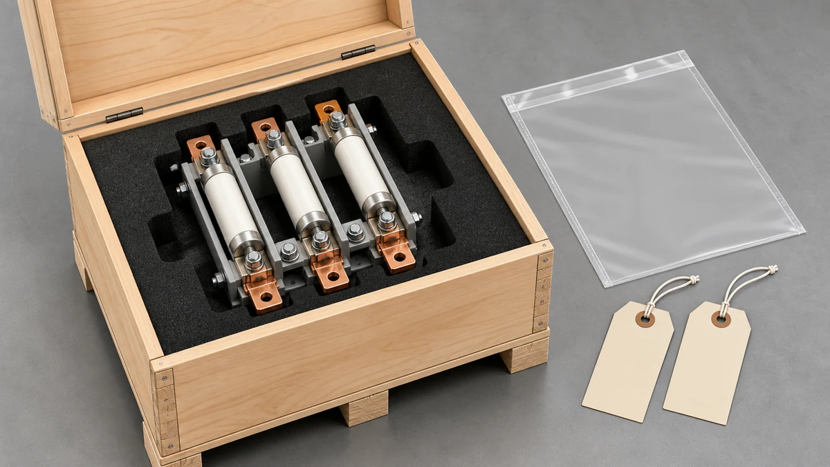
Send the request type, manufacturer, equipment model/year, part reference, ratings, quantity, destination, required date, and any drawing or photo notes. The SUVELL team will review the request.
Email: admin@suvell.com
Phone: +86 189 6871 1705
Factory: No.208 Wei 12 Rd, Yueqing Economic Development Zone, Wenzhou, Zhejiang, China
Bay-O-Net Fuse vs Current-Limiting Fuse: How the Protection Roles Work Together
Bay-O-Net and backup current-limiting fuses perform complementary roles in a coordinated transformer protection scheme. This comparison explains the duty split and the fuse references, time-current curves, transformer parameters, and source fault data needed to assess a replacement without relying on nominal ampere ratings alone.
In the coordinated scheme discussed here, the Bay-O-Net covers overloads and secondary faults within its rating, while the backup fuse addresses higher fault currents.
Coordination depends on the specific fuse curves, transformer data, and available fault current, rather than a universal pairing by ampere rating.
Record both installed fuse references and their mounting arrangement before replacement, and have substitutions checked against the approved coordination study.
A Bay-O-Net fuse and a current-limiting fuse are not competing options — they serve distinct fault-clearing roles in a coordinated two-fuse scheme. The Bay-O-Net handles overloads and secondary faults within its interrupting rating, while the current-limiting fuse clears high-level fault currents that exceed the Bay-O-Net's capability. Choosing one without the other, or selecting the pair without a coordination study, leaves part of the fault spectrum unprotected.
Attribute
Bay-O-Net Fuse
Current-Limiting (CL) Fuse
Primary role
Overload and secondary fault clearing
High-level internal fault clearing
Interrupting mechanism
Expulsion / arc extinction in air
Sand-filled current-limiting element
Fault current range
Low-to-medium (within interrupting rating)
High-level (backup to Bay-O-Net)
Replaceability in field
Yes — designed for live-line replacement
No — typically requires de-energization
Visible indication
Yes — ejected fuse link or blown indicator
Not externally obvious without inspection
Coordination dependency
Must not operate for faults CL fuse owns
Must not operate for faults Bay-O-Net owns
Mounting location
Externally accessible fuse holder
Series-connected, typically internal or enclosure-mounted
What Each Fuse Actually Does During a Fault
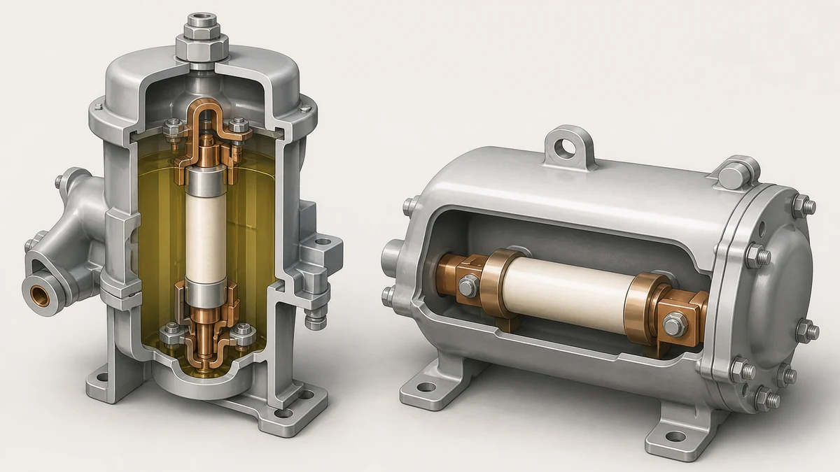
The Bay-O-Net fuse is an expulsion-type device. When the fusible element melts, it initiates an arc inside a fiber or melamine tube; the arc draws in air, generates gas, and expels hot gases and the melted element to extinguish the arc. The physical ejection of the fuse link is the visible indication crews rely on for field diagnosis. Its time-current characteristic is relatively slow, which means it will ride through normal transformer inrush and overload events long enough to avoid nuisance operations — but that same characteristic limits how much fault current it can safely interrupt.
The current-limiting fuse works on a different principle. It uses a silver or tin fusible element packed in a silica sand matrix inside a sealed ceramic or glass-fiber body. When fault current rises rapidly through the element, the sand quenches the arc almost instantaneously, limiting both the peak let-through current and the clearing time to a fraction of a cycle. This sub-cycle response is what gives it a current-limiting effect: the downstream equipment never sees the full prospective fault current. The tradeoff is that the device is consumed in the process and has no visible external indication of operation — the transformer must be inspected and the fuse tested or replaced based on system evidence rather than visual confirmation.
These two operating mechanisms explain why the devices occupy different parts of the fault spectrum. The Bay-O-Net's expulsion process depends on arc extinction and cannot handle the arc energy at high fault currents. The current-limiting fuse's sealed, sand-filled design handles high arcing energy but is unsuitable as the first line of defense for sustained overloads because its fast response would operate on legitimate inrush or overload events that the transformer can survive.
The Coordinated Two-Fuse Scheme and Why Coordination Is Not Optional
Eaton describes a two-fuse protection scheme in which the Bay-O-Net clears secondary faults and overload currents, while the series-connected current-limiting backup fuse clears high-level fault currents associated with stated internal-equipment-failure conditions. The word "series-connected" is operationally important: both fuses carry load current continuously, and only their time-current characteristics determine which one operates for a given fault.
Eaton states explicitly that the pair must be coordinated so the current-limiting fuse operates only for the stated internal-equipment-failure condition — meaning high-level faults where the Bay-O-Net's interrupting rating would be exceeded. If coordination is not verified, two failure modes become possible. First, the current-limiting fuse may operate for faults the Bay-O-Net could have cleared, turning a field-replaceable maintenance event into a de-energization and inspection job. Second, the Bay-O-Net may be asked to interrupt a fault above its rating, potentially failing violently.
Coordination also has a lower boundary. The Bay-O-Net's minimum melting curve must stay below the current-limiting fuse's minimum melting curve across the shared fault current range, with sufficient margin to account for manufacturing tolerances and pre-loading effects. A Bay-O-Net that has been operating at elevated temperature for an extended period will have a faster effective characteristic than its published curve, which can erode the coordination margin over time.
Configuration Dependencies: Where the Scheme Can Break Down
The two-fuse scheme is not a self-contained module. Its behavior depends on several external variables that interact with the fuse characteristics:
**Transformer kVA and impedance.** Transformer impedance determines the secondary fault current as seen from the primary. A low-impedance transformer produces higher available fault current on the primary side for a given secondary fault, which shifts the fault current range where the current-limiting fuse must operate. Selecting fuse ratings against the transformer nameplate alone, without accounting for impedance, routinely produces miscoordinated pairs.
**Source available fault current.** The current-limiting fuse's operating range starts at the upper end of the Bay-O-Net's interrupting rating and extends to the source's maximum available fault current. If a substation upgrade increases available fault current, a previously coordinated pair may no longer cover the full fault spectrum without re-evaluation.
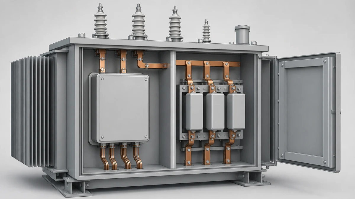
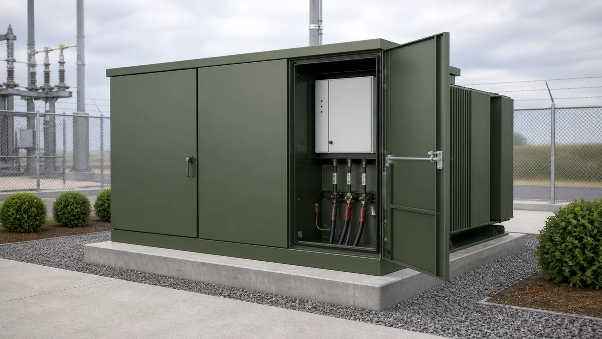
**Mounting configuration.** Eaton's fusing-philosophy document emphasizes that coordination is configuration-specific. The physical arrangement — whether the current-limiting fuse is internal to the transformer tank, mounted in a separate compartment, or in a series fuse holder external to the pad-mounted cabinet — affects both the fault current distribution and the ease of inspection. Internal current-limiting fuses in a sealed transformer require opening the tank for replacement, so an undetected operation leaves the transformer running with only one-half of its protection scheme intact.
**Secondary loading patterns.** Recurring overloads accumulate thermal damage in the Bay-O-Net element over time. A Bay-O-Net that has been cycled through repeated high-load events without replacement may operate significantly faster than its published curve, which can cause it to miscoordinate with the current-limiting fuse or fail to ride through legitimate inrush.
Reading the Time-Current Curves: What the Coordination Study Must Verify
Eaton's fusing-philosophy document presents coordination as a configuration-specific engineering exercise using transformer data and time-current curves — not a universal ampere-rating rule. The practical steps for verifying coordination are:
1. Obtain the transformer's kVA rating, primary voltage, impedance (percent), and full-load current.
2. Obtain the source's maximum and minimum available fault current at the transformer primary terminals.
3. Plot the Bay-O-Net's minimum melting curve and maximum clearing curve on the same time-current graph.
4. Plot the current-limiting fuse's minimum melting curve on the same graph.
5. Verify that the Bay-O-Net's maximum clearing curve stays below the current-limiting fuse's minimum melting curve at all currents within the Bay-O-Net's interrupting rating — confirming the Bay-O-Net clears before the current-limiting fuse begins to melt.
6. Verify that the maximum fault current the Bay-O-Net is expected to interrupt does not exceed its published interrupting rating.
7. Confirm that the current-limiting fuse will operate for all fault currents above the Bay-O-Net's interrupting rating and up to the maximum available fault current.
If the curves cross in steps 5 or 7, the rating of one or both fuses must change, or the transformer impedance and source data must be re-examined for errors. A crossing is not a matter of acceptable margin — it indicates the scheme will not perform as designed for some subset of fault conditions.
Failure Modes and Installation Risks
**Bay-O-Net operated above its interrupting rating.** If the available fault current exceeds the Bay-O-Net's interrupting rating and the current-limiting fuse fails to operate first (due to a miscoordinated or incorrectly installed pair), the Bay-O-Net will attempt to interrupt a current beyond its design limit. The result can be a violent expulsion failure, a sustained arc, or transformer damage from fault energy that was not cleared. This is the primary catastrophic risk in a miscoordinated scheme.
**Undetected current-limiting fuse operation.** Because the current-limiting fuse has no visible external indication, crews may restore the Bay-O-Net after a fault and re-energize the transformer without realizing the current-limiting fuse also operated. The transformer is then energized with only the Bay-O-Net in place — no backup for high-level faults. A post-fault inspection protocol that includes testing or replacing the current-limiting fuse is not optional.
**Thermally degraded Bay-O-Net.** A Bay-O-Net that has been carrying sustained heavy load or has experienced repeated near-threshold overcurrents may have accelerated aging on the fusible element. Its effective time-current characteristic shifts faster than the published curve, potentially causing it to operate during inrush or recoverable overloads, or causing it to miscoordinate by operating within a range the current-limiting fuse was expected to own.
**Incorrect Bay-O-Net ampere rating for the transformer.** Oversizing the Bay-O-Net to reduce nuisance operations has a direct cost: the upper end of the overload protection moves, leaving the transformer exposed to sustained overloads it cannot tolerate. Undersizing causes nuisance operations on inrush. Either condition is visible in the coordination study but not obvious from the nameplate alone.
Data Required Before an RFQ or Replacement Decision
Transformer kVA, primary and secondary voltage, and percent impedance from the nameplate or factory test report
Source maximum available fault current at the primary terminals (from the utility or system study, not estimated)
Existing Bay-O-Net and current-limiting fuse manufacturer, catalog number, and ampere rating for both devices — replacing one half of a previously coordinated pair with a different manufacturer's product requires re-verification of the coordination curves
Physical mounting configuration (internal, compartment-mounted, or external series holder) and whether the current-limiting fuse is accessible without de-energizing
Operational history: Has the Bay-O-Net operated recently? Has the current-limiting fuse been tested or replaced after any fault event?
Applicable utility or owner specification for fusing philosophy, since some utilities mandate specific fuse families or coordination margins that supersede the general approach
Substituting a "similar" Bay-O-Net by ampere rating alone, without confirming that the replacement device's time-current curves match the original and coordinate with the installed current-limiting fuse, introduces coordination uncertainty that may not surface until a fault occurs.
FAQ
What is a Bay-O-Net fuse?
A Bay-O-Net fuse is an expulsion-type fuse used primarily on pad-mounted and submersible distribution transformers. It uses arc extinction in a gas-generating tube to interrupt overload and secondary fault currents within its rated interrupting capacity. The fuse link is externally accessible, designed for field replacement under certain operating conditions, and produces a visible indication of operation when the link ejects or a blown indicator deploys.
What is a current-limiting fuse in transformer protection?
A current-limiting fuse is a high-interrupting-capacity device that uses a sand-filled fusible element in a sealed body to quench fault arcs in sub-cycle time. In transformer protection it functions as a backup to the Bay-O-Net, operating only for high-level fault currents that exceed the Bay-O-Net's interrupting rating. Its defining characteristic is that it limits the peak let-through current seen by the transformer and connected equipment, reducing fault energy even for very high available fault currents.
What is the difference between Bay-O-Net fuse vs current-limiting fuse protection roles?
The Bay-O-Net covers the lower fault current range — overloads and secondary faults — while the current-limiting fuse covers the upper range associated with internal transformer failures and high available fault currents. They are connected in series and must be coordinated so each device operates only in its intended range. Operating the Bay-O-Net above its interrupting rating or operating the current-limiting fuse for faults the Bay-O-Net should clear are both failure modes that the coordination study is designed to prevent.
What is fuse coordination in transformer protection?
Fuse coordination is the process of verifying that two series-connected fuses have time-current characteristics that produce the correct operating sequence for every fault current level in the system. For the Bay-O-Net and current-limiting fuse pair, coordination means the Bay-O-Net's maximum clearing curve remains below the current-limiting fuse's minimum melting curve across the Bay-O-Net's full interrupting range, and that the current-limiting fuse will operate before the Bay-O-Net is asked to clear fault currents beyond its rating. Eaton's fusing-philosophy documentation establishes that this is a configuration-specific engineering exercise, not a table-lookup process.
What is the risk of replacing only one fuse in a coordinated pair?
Replacing only the Bay-O-Net without verifying that the replacement device's time-current curves are compatible with the installed current-limiting fuse can invalidate the original coordination. Different manufacturers' Bay-O-Net products at the same ampere rating can have meaningfully different minimum melting and maximum clearing curves. The coordinated behavior depends on the specific curve shapes, not the nominal rating, so any substitution requires re-checking the coordination curves against the installed current-limiting fuse before returning the transformer to service.
LEO Chen
With more than 20 years of industry experience, LEO Chen has worked with major companies on switchgear, transformer components and medium-voltage equipment projects. He contributes practical guidance for engineers and sourcing teams, with a focus on clear selection criteria, application context and the information needed to prepare an informed RFQ. Connect with LEO on LinkedIn.