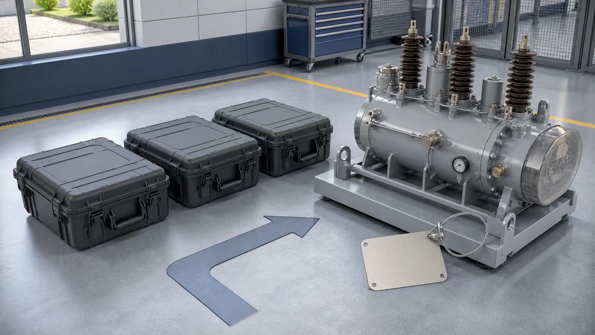
Send the request type, manufacturer, equipment model/year, part reference, ratings, quantity, destination, required date, and any drawing or photo notes. The SUVELL team will review the request.
Email: admin@suvell.com
Phone: +86 189 6871 1705
Factory: No.208 Wei 12 Rd, Yueqing Economic Development Zone, Wenzhou, Zhejiang, China
Transformer Outage Readiness: Building a Component Replacement Inventory
A transformer replacement inventory works only when stocked components suit the installed fleet. This guide connects equipment records and interface checks with criticality, supplier lead times, storage conditions, and shared-spare compatibility, helping maintenance teams keep the inventory aligned with changing assets and replacement options.
Link each candidate transformer spare to the installed unit’s drawings, component records, and verified mechanical and electrical interfaces.
Size stock using asset criticality, failure history, current supplier lead times, and confirmed compatibility across the fleet.
Record storage and shelf-life requirements, and review the inventory after equipment changes, spare consumption, or supplier part revisions.
Designing a transformer spare parts list is not a universal exercise. The right inventory depends on your installed equipment, your site's criticality, your utility's lead times, and the specific interfaces built into each transformer — IEC 60076-1:2011 defines the scope and testing framework for power transformers but explicitly does not mandate a universal component-replacement inventory applicable to every installation. Start from your transformer's nameplate data, its design drawings, and manufacturer documentation; use standards and peer practice as a framework for deciding what to carry, not as a bill of materials.
Why Installed-Unit Data Drives Every Inventory Decision
Generic spare parts lists circulate widely in the industry, but they carry a hidden risk: components that look interchangeable often are not. Bushings, tap changers, cooling fans, and pressure-relief devices are all sized and rated to match a specific transformer's design voltage, current, insulation class, and mechanical interface. A bushing that fits the flange dimensions of one manufacturer's 69 kV transformer may present a completely different capacitance profile, creep distance, or oil-barrier geometry compared to what the factory supplied.
The consequence is that procurement decisions made from a generic list can produce spares that pass a visual check but introduce subtle incompatibilities. Partial discharge behavior, thermal class, and dielectric test results are all part of a certified test report — and that report is specific to the part, not to a generic type designation. Hitachi Energy, for example, provides a product-specific route for certified test reports and bushing cross-reference or dimensional searches, requiring that product records and manufacturer documents be checked before any candidate spare is approved for an installed transformer. That practice reflects the broader principle: approval happens at the component-to-transformer pairing level, not at the category level.
The implication for procurement is direct. Before any spare is added to a stocking plan, the reviewer needs the transformer's factory test report, its outline drawing, its component datasheets, and the manufacturer's approved-equivalent list. These documents determine whether a candidate part is truly interchangeable or merely dimensionally similar.
IEC 60076-1 as a Framework Boundary, Not a BOM
IEC 60076-1:2011 covers the specification, marking, testing, liquid-preservation systems, tank tests, and condition-monitoring facilities for single-phase and three-phase power transformers. It is the governing standard for how a transformer is characterized and verified as a product. What it does not do is prescribe which components a user must stock as field replacements.
This distinction matters when procurement teams are asked to justify an inventory to finance or operations stakeholders. The standard provides the testing vocabulary — insulation levels, temperature rise, no-load and load-loss measurements — that should be used when verifying that a candidate spare matches the original specification. It does not, however, create a universal replacement schedule. Two transformers with identical kVA ratings and identical voltage classes can have substantially different spare-parts requirements if they were designed by different manufacturers, use different cooling configurations, or were ordered to different accessory specifications.
Using IEC 60076-1 correctly means leveraging its test definitions to frame the acceptance criteria for a candidate spare, not treating its scope as a checklist of parts to order. When evaluating a replacement bushing or a conservator bladder, the relevant question is whether the candidate meets the same dielectric and dimensional requirements established in the original type test — and that answer comes from comparing certified documentation, not from the standard itself.
Functional Component Categories and Their Replacement Logic
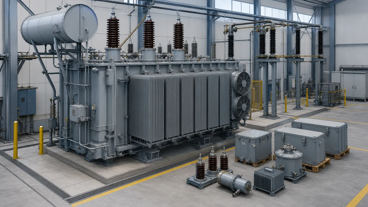
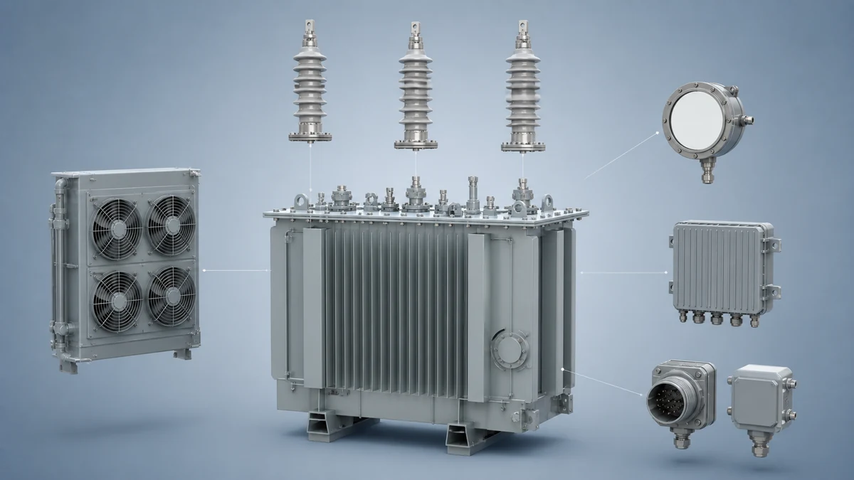
A transformer spare parts list organized by functional category makes procurement reviews easier and reduces the risk of stocking the wrong variant. The following categories represent the decision logic that applies to each, not a prescribed list.
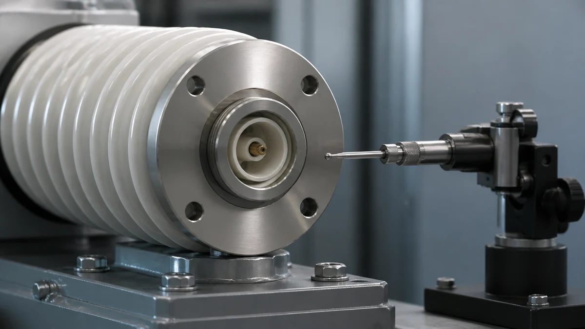
**Bushings** are the highest-priority spare in most high-voltage transformer programs. They fail from insulation degradation, moisture ingress, mechanical damage, and flashover. Because bushing ratings are tied to voltage class, current rating, creep distance, and mounting flange geometry, a replacement must match all four parameters. Capacitance and tan-delta values from the certified test report are the primary verification criteria. For bushings above 115 kV, stocking one spare per winding voltage level per critical transformer is a common practice; below that threshold, the decision depends on lead time from the manufacturer.
**Tap changer components** — contacts, drive mechanisms, oil compartments, and control relays — require particular attention because on-load tap changers (OLTCs) are the highest-maintenance component in most power transformers. The replacement logic differs between OLTCs and de-energized tap changers (DETCs): OLTCs have wear parts on a defined maintenance cycle, while DETCs are typically only replaced after a fault or if corrosion is detected during inspection. Stocking contact sets and the manufacturer's recommended minor-overhaul kit for each OLTC design in your fleet is standard practice; major mechanical assemblies are typically repaired by specialists rather than swapped from inventory.
**Cooling system components** — fans, pumps, radiators, and control panels — have shorter lead times than insulation components and are more interchangeable across units from the same manufacturer. The risk here is control voltage and contactor compatibility: a replacement fan rated for the correct airflow but wired for a different voltage or using a different motor frame will require rewiring or adapter fabrication, adding time during a restoration. Standardizing cooling components across a transformer fleet at the procurement stage, rather than at the spare-parts stage, is the most effective mitigation.
**Pressure-relief devices and buchholz relays** are safety devices with both mechanical and electrical interfaces. The mechanical interface must match the transformer's tank fitting dimension; the electrical interface must be compatible with the protection relay scheme. A replacement device that vents at the correct pressure but uses a different flange pattern or a different contact configuration creates a delay when it matters most.
**Gaskets and sealing materials** are low-cost items with significant restoration-time impact if not stocked. Gasket material compatibility with the transformer's insulating fluid — mineral oil, natural ester, or synthetic ester — must be confirmed. Nitrile materials that are acceptable for mineral oil can degrade rapidly in ester fluids.
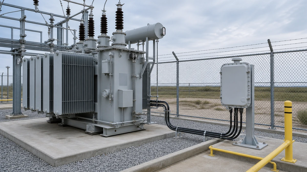
**Control and protection wiring harnesses, fuses, and terminal boards** are frequently overlooked until a fault event reveals that the failed component is a low-cost item with a six-week lead time. These are candidates for regional shared-spare pools where multiple similar transformers are operated by the same utility.
Criticality and Lead Time as the Primary Sizing Inputs
No spare parts plan is cost-justified without a criticality rating. The basic framework pairs consequence of failure with component lead time to produce a stocking priority.
Criticality Factor
High Priority
Medium Priority
Lower Priority
Consequence of failure
Loss of supply to critical load; no bypass
Reduced capacity; partial bypass available
Redundant path available
Lead time from OEM
> 20 weeks
8–20 weeks
< 8 weeks
Failure rate history
Field failures documented in fleet
Occasional failures in similar units
Rare; primarily end-of-life failure mode
Spare compatibility
Unit-specific; no cross-fleet reuse
Compatible across 2–3 units
Compatible across entire fleet
Components that score high on all four factors belong in on-site or regionally pooled inventory. Components with low consequence or short lead times are candidates for just-in-time procurement, freeing capital for high-priority items.
Lead time for power transformer components varies considerably by manufacturer, voltage class, and market conditions. Bushings for transmission-class transformers routinely carry lead times of six months or longer during periods of high demand. High-voltage winding repairs and complete active-part replacements can extend to twelve to eighteen months. These lead times mean that a criticality analysis conducted during normal operations, not after the first failure event, is the only way to avoid extended outages.
The Manufacturer Documentation Review Before Any RFQ
Issuing a request for quotation without completing the documentation review first is one of the most common sources of spare-parts mismatches. The review is not a bureaucratic step; it is the mechanism that converts a generic component category into a specified part.
The minimum documentation set for a bushing, tap changer component, or cooling assembly includes the transformer's outline drawing identifying the component's mounting interface, the component's original datasheet or type designation, the manufacturer's list of approved equivalents or cross-references, and — for bushings and other high-voltage insulation components — the certified type test report for both the original and the proposed replacement. Hitachi Energy's cross-reference and dimensional search capability is a practical example of how this process can be formalized: the reviewer uses manufacturer tools to confirm that the candidate part maps to the installed unit's specific product record, not merely to a similar type designation.
For components from manufacturers that have been acquired, renamed, or discontinued, the documentation trail can be interrupted. In these cases, the path forward is dimensional and electrical verification against the original test report, not assumption of equivalence from a product name change. Engaging the current manufacturer's technical support team before the RFQ is the right step when the documentation chain is unclear.
Verification Boundaries for Inspection and Installation
This guide addresses the evidence, documentation, and decision framework for spare-parts planning. It does not cover live-operation procedures, switching sequences, torque specifications, oil-handling steps, or protection relay setpoint adjustments. Those activities are governed by model-specific approved procedures from the transformer manufacturer and the site's operating authority, and they require qualified personnel following those documents.
For inspection activities — incoming inspection of a received spare, pre-installation checks on a replacement bushing, or verification of a tap changer contact set — the key questions are whether the received component matches the specified part number and certified test report, whether the component's condition is within the manufacturer's acceptance criteria after shipping and storage, and whether any shelf-life requirements for sealing materials or insulating fluid have been met. These are documentation and measurement checks that can be completed before the installation window, reducing time pressure during a restoration.
Storage conditions are often underspecified in spare-parts programs. Bushings stored incorrectly can absorb moisture that will not be detected until a tan-delta test is performed. Replacement mineral oil must be tested for moisture content and dielectric strength before use. Gasket materials have temperature and UV exposure limits. Documenting storage requirements for each stocked component at the time of procurement, rather than discovering them during a restoration event, is an engineering practice that meaningfully reduces restoration risk.
Organizational and Governance Considerations
A transformer spare parts list is a living document, not a one-time procurement decision. Three organizational practices keep the inventory aligned with the installed fleet.
First, the spare-parts review should be triggered by any change to the transformer fleet — a new unit, a replacement, or a design modification. When a new transformer is commissioned, the spare-parts implications of its specific accessory configuration should be resolved before the warranty period ends, while the manufacturer's documentation team is still engaged.
Second, spares used during a restoration event should be restocked through the same documentation review process used for initial procurement, not by reordering from the last purchase order. Manufacturer product changes, cross-reference updates, and type test revision cycles mean that a part ordered three years ago may have a current equivalent that is not identical to the original.
Third, shared-spare pool agreements between neighboring utilities or within a large transmission operator's regional structure can reduce per-unit carrying costs significantly for high-cost, low-probability components like complete tap changer mechanisms or spare core-and-coil assemblies. These agreements require a documented compatibility matrix — confirming that the pooled spare can be installed in each transformer in the pool — and a clear mobilization protocol. The compatibility matrix is built from the same manufacturer documentation review described above; without it, a shared-spare agreement is a financial arrangement without an engineering basis.
Practical Review Questions Before Finalizing the Inventory
The following questions structure a pre-procurement review for each candidate spare. They are not a checklist to be completed in sequence; they are the decision gates that determine whether a spare is ready to procure, requires additional documentation, or should be deferred.
Does the candidate part number appear on the transformer manufacturer's approved-replacement or cross-reference list for this specific installed unit? If not, what dimensional and electrical verification will be performed before the part is approved?
Is a certified type test report available for the candidate spare, and does it confirm that the candidate's electrical ratings, insulation class, and interface dimensions meet or exceed the original specification? For bushings, does the capacitance value fall within the range specified for the installed transformer's protection scheme?
What are the storage requirements for the candidate spare, and can the storage facility meet them? Who is responsible for periodic condition checks — specifically, incoming moisture tests for bushings and oil, shelf-life tracking for elastomers?
What is the current lead time from the OEM for this component, and has it been validated with the manufacturer or distributor recently rather than assumed from a previous quote? Has the manufacturer been acquired or changed the product line since the last procurement?
Has the spare-parts program been reviewed with the protection and control team to confirm that replacement relay interfaces, control wiring, and communication protocols are compatible with the installed protection scheme?
If the spare is intended to serve a shared-spare pool, has a compatibility matrix been formally documented and reviewed by engineering for each transformer in the pool?
—
FAQ
What is a transformer spare parts list?
A transformer spare parts list is an engineering and procurement document that identifies the specific components stocked for a given installed transformer or transformer fleet to support rapid restoration after a failure. Unlike a generic bill of materials, a proper spare parts list is developed from the installed transformer's nameplate data, manufacturer documentation, and a criticality analysis that weighs failure consequence against component lead time. It is not a universal or mandatory inventory — IEC 60076-1:2011, the primary power transformer standard, defines testing and specification requirements but does not prescribe a replacement component inventory applicable to all installations.
What is the difference between an OLTC and a DETC for spare-parts purposes?
An on-load tap changer (OLTC) operates under load and executes thousands of switching operations per year, producing wear on its contacts and arcing components. It requires periodic maintenance, and its wear parts — contact sets, transition resistors, drive mechanism components — are candidates for scheduled replacement spares. A de-energized tap changer (DETC) operates only when the transformer is de-energized and experiences far less mechanical wear. DETC spares are typically procured reactively after a fault or corrosion finding rather than stocked preventively, though the specific decision depends on the transformer's criticality and the manufacturer's maintenance guidance.
What is the role of a certified test report in spare-parts approval?
A certified test report documents that a specific component — most critically bushings and other high-voltage insulation parts — was manufactured to a defined specification and passed defined type tests. For bushing replacements, the test report confirms the capacitance value, tan-delta, power frequency withstand, and lightning impulse levels for that specific part. Because these values must match the installed transformer's design and its protection relay settings, a candidate spare cannot be approved from a catalog description alone. Hitachi Energy provides a product-specific search path for certified test reports and cross-references that illustrates how this verification is formalized by a major manufacturer: the review traces to a product record, not a generic type category.
What is the right way to handle spare parts for transformers with discontinued manufacturer support?
When a transformer manufacturer has been acquired, restructured, or has discontinued support for a product line, the documentation chain supporting spare-parts equivalence can be interrupted. The safe path is to obtain the original outline drawing, component datasheets, and type test reports before the manufacturer's records become inaccessible, and to engage the current entity — the acquiring company or an authorized service organization — to establish a formal cross-reference to currently available equivalents. Dimensional and electrical verification against the original test report is required when a direct manufacturer cross-reference is unavailable. Assuming equivalence from a shared trade name or similar catalog description without documentation review introduces unacceptable risk for high-voltage components.
What is the minimum documentation needed before issuing an RFQ for a bushing replacement?
Before issuing a request for quotation for a bushing replacement, the reviewer needs four documents: the installed transformer's outline drawing that identifies the bushing's mounting flange geometry, current rating, and voltage class; the original bushing's datasheet or type designation; the manufacturer's approved cross-reference or equivalent list for that transformer; and the certified type test report for both the original and the proposed replacement bushing. Without the test report comparison, the procurement process cannot confirm that the candidate spare meets the dielectric performance requirements of the installed transformer and its protection scheme.
LEO Chen
With more than 20 years of industry experience, LEO Chen has worked with major companies on switchgear, transformer components and medium-voltage equipment projects. He contributes practical guidance for engineers and sourcing teams, with a focus on clear selection criteria, application context and the information needed to prepare an informed RFQ. Connect with LEO on LinkedIn.