Send the request type, manufacturer, equipment model/year, part reference, ratings, quantity, destination, required date, and any drawing or photo notes. The SUVELL team will review the request.
Email: admin@suvell.com
Phone: +86 189 6871 1705
Factory: No.208 Wei 12 Rd, Yueqing Economic Development Zone, Wenzhou, Zhejiang, China
Which Switchgear Spares Should Be Staged for a Planned Maintenance Outage?
Switchgear outage spares should follow the installed assembly and the work planned for it. This guide links parts manuals, inspection history, criticality, and lead times with compatibility checks, including the settings files and software needed to make a staged numerical relay usable.
Build the outage spares list from panel-specific parts manuals, as-built schematics, maintenance findings, and the planned work scope.
Prioritize compatible components by failure consequence and lead time, checking coil voltages, CT/VT requirements, fuse types, and physical fit.
Stage relay settings backups, compatible configuration software, and installation procedures alongside any replacement hardware that needs them.
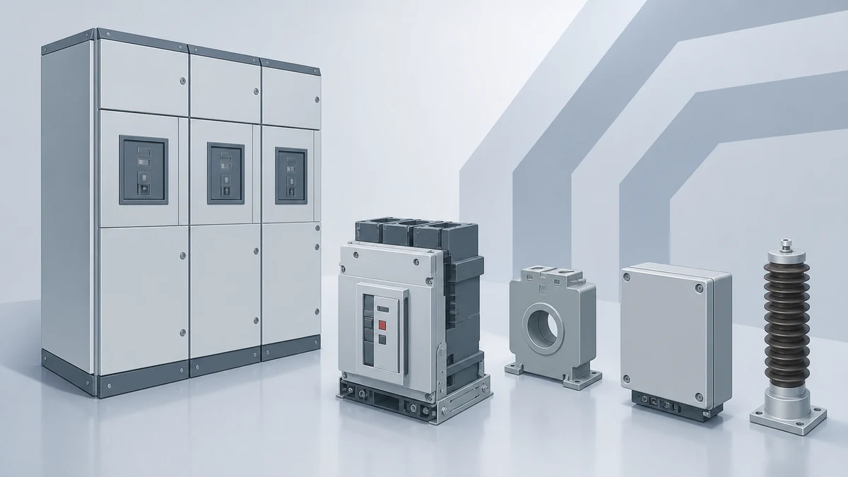
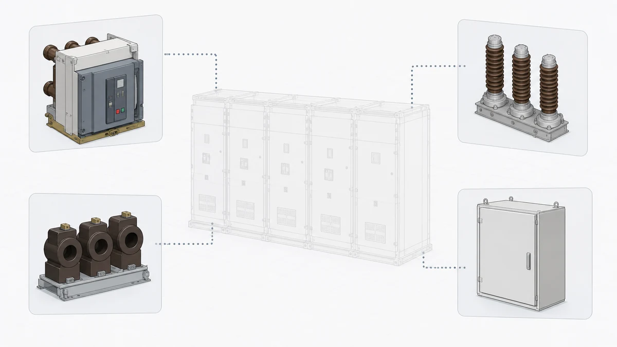
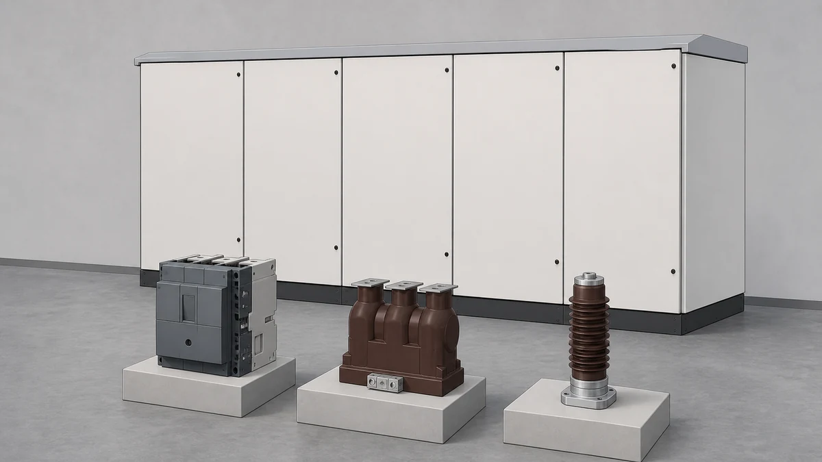
Stage spares against your installed assembly's documentation — the nameplate, single-line diagram, and OEM parts manual — not against a generic bill of materials. A catalog like Schneider Electric's medium-voltage components range tells you what exists in a product family; IEC 62271-200:2021 sets performance and type-test requirements for metal-enclosed assemblies. Neither document prescribes what you must stock for a specific outage. The right switchgear spare parts list is always equipment-specific, risk-weighted, and tied to your maintenance scope.
Why Generic Spare Parts Lists Mislead More Than They Help
The temptation to download a "standard" switchgear spares list is understandable, but it creates two real risks: over-stocking parts that don't fit your assembly, and missing assembly-specific items that a generic list never mentions.
IEC 62271-200:2021 applies to AC metal-enclosed switchgear in the ranges it defines, covering type-testing, ratings, and assembly integrity requirements. It does not contain a spares schedule. Its relevance to outage planning is indirect: it tells you what properties a replacement component must meet — insulation level, rated current, rated short-circuit withstand — so you know what the replacement must be rated for, not what to pull from shelf.
Schneider Electric's medium-voltage components catalog (version 9.0) presents a broad range of switching, protection, instrument-transformer, fuse, and control components for MV switchgear. It is an identification source. It lets you confirm that a replacement part exists in the current product family, and it gives you the catalog reference you need for a procurement query. It is not a compatibility proof for your installed switchgear. Component fitment depends on frame generation, bus configuration, secondary wiring scheme, and protection relay type — none of which a catalog communicates for your specific panel.
The practical consequence: always trace a candidate spare back to your as-built drawings and OEM parts manual before staging it.
The Four Documents That Actually Drive Your Spares Decision
Before building any list, assemble these four sources for each switchgear assembly in scope:
**OEM parts manual or illustrated parts breakdown (IPB).** This is the primary reference. It ties part numbers to assembly positions, gives interchangeability notes, and flags consumables versus life-limited components.
**As-built single-line and secondary schematic drawings.** These confirm the protection relay type, CT/VT ratio and burden, control voltage, and auxiliary contact scheme. A replacement relay or current transformer that doesn't match these parameters isn't a spare — it's a modification.
**Maintenance history and inspection records.** Historical defects on your own fleet are the strongest predictor of what will fail during or after outage work. If arc-chute erosion has appeared twice in five years on a specific circuit breaker, that's a stocking signal.
**Outage scope document.** The spares list follows the work scope. An outage scoped to contact inspection and vacuum interrupter testing requires different staged parts than one that includes bus section maintenance or protection relay testing.
None of these documents is a substitute for the others. The OEM manual gives you the part number; the schematic tells you whether the rated parameter is right; the history tells you the probability; the scope tells you what's physically accessible.
Component Categories and the Decision Logic for Each
Switching and Interrupting Components
Vacuum interrupters are the highest-consequence spare in most MV drawout breaker assemblies. They are not field-repairable; contact erosion beyond the OEM wear limit requires replacement. The wear indicator — typically a mechanical gauge on the pole — must be read against the OEM acceptance criterion, not a generic number. If an interrupter is near its wear limit, staging a replacement before the outage avoids a second forced outage while a part is sourced.
Spares decisions for vacuum interrupters require the breaker type, frame generation, and rated symmetrical interrupting current from the nameplate. Catalog identification of the correct part is a starting point; fitment confirmation against the OEM parts manual is the required step. Model-specific approved procedures govern the actual replacement sequence — contact gap measurement, mechanical operation verification, and dielectric testing after installation.
Operating mechanisms accumulate wear on charging springs, trip latches, and closing coil plungers. Closing coils and trip coils are relatively low-cost, high-failure-consequence items that are worth staging as consumables for any outage that includes operation testing. Check OEM guidance on whether coil replacement requires mechanism recalibration before adding this spare to your list.
Instrument Transformers
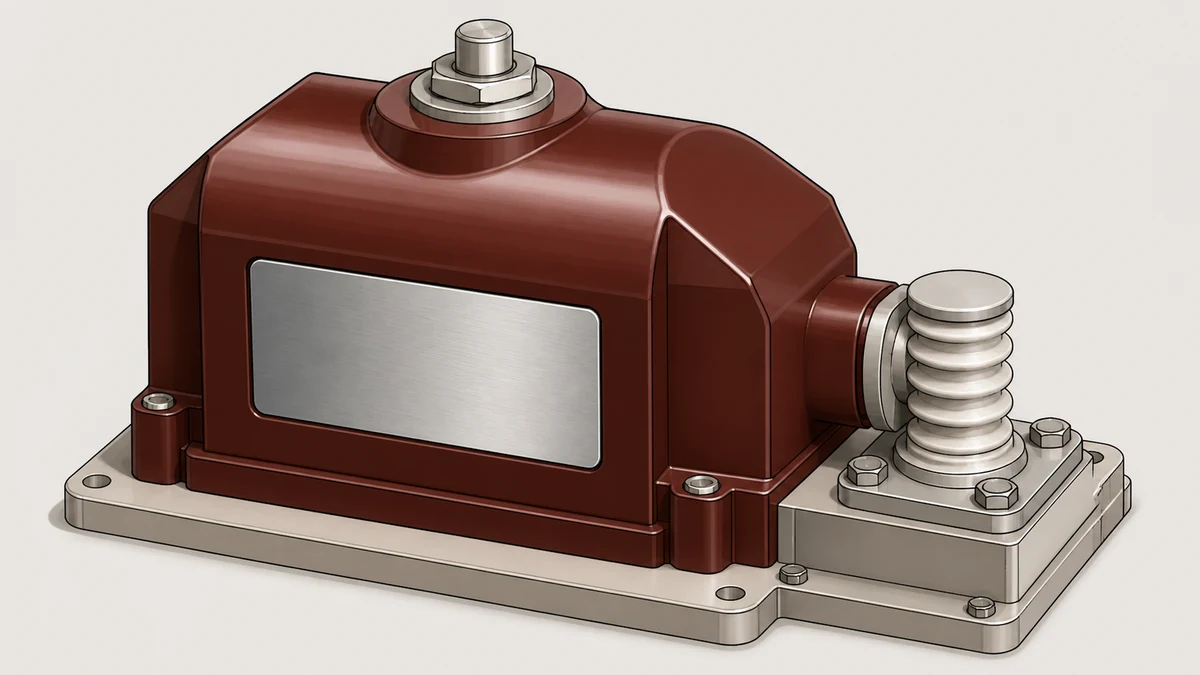
Current transformers and voltage transformers in metal-enclosed switchgear are typically panel-mounted and may be bus-connected. Replacements must match the original in: rated primary current or voltage, secondary burden and class, insulation level, and physical interface dimensions.
The secondary class is not a minor parameter. Substituting a metering-class CT for a protection-class CT — or vice versa — alters the accuracy limit factor and can affect the reach of overcurrent protection. This is a relay coordination issue, not just a metrology one. Before staging a CT or VT as a spare, confirm the class and burden from the secondary schematic, not from a nameplate photograph alone.
VTs used for protection trip signals carry an additional interface dependency: the fuse type and rating in the VT circuit may be assembly-specific. Stage the fuse alongside the VT if your outage scope includes VT removal.
Fuses and Protection Components
HV fuses in MV switchgear are type- and rating-specific, and mixing manufacturer or type within a fusegear assembly can affect clearing characteristics and mechanical fit. Stage exact replacement fuses matched to the installed type and rating. If your fuse supplier has changed since original installation, obtain a written interchangeability statement before staging the new-source fuse.
Protection relay spares decisions depend heavily on whether your relay is a discrete electromechanical or static type versus a modern numerical IED. Numerical IEDs hold settings in firmware; a replacement relay arrives with factory defaults. Before staging a relay replacement, confirm that you have the relay settings file (exported from the installed relay) and the configuration software version available on-site. The spare relay itself is only part of what you need.
Secondary Wiring, Control Voltage, and Auxiliary Items
Control power fuses and MCBs protecting secondary circuits are low-cost, high-turnover items. Stage a set matched to the installed panel's secondary schematic. Auxiliary relays and timers in trip and interlock circuits should be identified from the secondary schematic and staged if they are in the planned work scope or have a history of contact failure in your fleet.
Cable termination materials — heat-shrink ends, lugs, ferrules — are not glamorous, but a damaged termination found during outage work requires immediate repair. Stage a small quantity matched to the cable types in the panel's secondary wiring harness.
A Practical Staging Workflow
The workflow below organizes the decision process from documentation through procurement:
1. **Define the outage scope precisely.** A vague scope produces a vague spares list. Identify each panel, each functional zone (bus, feeder, bus coupler), and each planned work activity (visual inspection only; contact measurement; functional testing; relay testing; full strip-down).
2. **Pull the OEM parts manual for each assembly type.** Extract part numbers for all items in the planned work scope. Flag items marked as consumables or life-limited separately from structural components.
3. **Cross-reference the secondary schematic.** For every instrument transformer, relay, and control device in scope, verify the rated parameter. Note the control voltage, CT burden, and any firmware version dependencies for numerical relays.
4. **Screen against maintenance history.** For each candidate spare, check whether a failure of that component has been recorded on your own fleet. Elevate priority for items with recorded failures. Reduce priority for components on circuits with no access work planned and no defect history.
5. **Apply a lead-time and criticality filter.** Items with long procurement lead times and high consequence-of-failure scores justify a higher stock position. Items that are standard catalog stock with a 24-hour local availability don't need to be pre-staged in the same quantity.
6. **Confirm physical fitment before the outage, not during it.** For any replacement component — especially VTs, CTs, and interrupters — verify dimensional and electrical fitment against as-built drawings before the outage window opens. Finding a fitment issue at 2 a.m. during an outage is a much worse problem than finding it during a pre-outage engineering review.
What to Verify Before Issuing an RFQ
A procurement query for switchgear spares that omits assembly-specific parameters will return either a commercially-optimized substitute or a request for more information — at the worst possible time. The data to gather before an RFQ:
Data Element
Where to Find It
Why It Matters for the RFQ
OEM part number
OEM IPB / parts manual
Uniquely identifies the correct item for the installed assembly
Assembly type and year
Nameplate
Determines which product generation the part belongs to
Rated voltage and current
Nameplate / schematic
Defines minimum acceptable ratings for the replacement
CT/VT class and burden
Secondary schematic
Specifies protection or metering class requirement
Relay firmware version
Relay front display / HMI
Required if staging a relay replacement
Fuse type and source
Panel BOM or as-built
Prevents inadvertent type substitution in fusegear
Interchangeability notes
OEM parts manual
Flags when a newer part number supersedes an older one
Sending this data with the RFQ eliminates ambiguity, reduces the chance of receiving a non-conforming part, and gives the supplier the information needed to confirm availability of the correct item rather than a dimensional equivalent.
Risks of Incorrect or Unverified Spares
An unverified spare that is installed during a planned outage can introduce a failure mode that wasn't present before the work. The more common versions of this problem are worth naming directly.
A replacement vacuum interrupter with an incorrect contact gap will either fail to interrupt reliably at rated current or will wear prematurely. The error is typically invisible until the next fault or operation count audit.
A CT with the wrong accuracy limit factor will cause the protection relay to see a distorted fault current. The result is either under-reach (failure to trip) or over-reach (spurious trip) depending on the direction of the error. This is a protection coordination issue and requires engineering review to resolve after the fact.
A numerical relay installed with factory-default settings and energized is a protection gap. This failure mode is process-preventable: the settings file must be staged alongside the hardware.
A fuse of the wrong clearing characteristic installed in a fusegear assembly changes the discrimination between upstream and downstream devices. In a radial MV network this can cause a fault on a downstream feeder to propagate upstream and affect a larger load block.
None of these risks requires extraordinary precaution to manage. They all require that the spare be verified against the installed assembly's documentation before it is staged, not after it is installed.
Installation, Inspection, and Commissioning Boundaries
This guide covers the decision framework for spare selection and staging. The actual removal, installation, and commissioning of components in metal-enclosed MV switchgear are governed by model-specific OEM approved procedures, site safety rules, and applicable national regulations. Those procedures specify torque values, dielectric test levels, contact gap acceptance criteria, and functional test sequences that are assembly-specific and are outside the scope of a planning framework.
For any replacement component installed during a planned outage, confirm that: the approved procedure for that component and assembly type is available on-site before work begins; the technician performing the work is qualified and authorized for the specific task; and post-installation verification (insulation resistance, contact resistance, functional operation, and protection test as applicable) is completed and documented before the panel is returned to service. If a condition found during outage work differs from what was expected — a busbar connection showing discoloration not previously recorded, a CT showing an insulation reading outside the OEM acceptance range — escalate for engineering review rather than proceeding on judgment.
FAQ
What is a switchgear spare parts list?
A switchgear spare parts list is a documented inventory of replacement components staged before a planned maintenance outage for a specific installed switchgear assembly. It is derived from the OEM parts manual, as-built drawings, and outage scope, and it covers consumables, life-limited items, and high-risk components identified through maintenance history and criticality analysis. It is not a universal bill of materials; the correct list varies by assembly type, age, rated voltage, and maintenance scope.
What is the role of IEC 62271-200 in spares planning?
IEC 62271-200:2021 applies to AC metal-enclosed switchgear assemblies in its stated range and specifies type-testing requirements, rated characteristics, and assembly performance criteria. It does not contain a spares schedule. Its practical relevance to spares planning is that it defines what performance a replacement component must meet — insulation level, short-circuit withstand, rated current — so engineering staff can confirm that a candidate replacement is correctly rated for the installed assembly. Spares planning itself must be tied to the installed assembly, its documentation, and the responsible maintenance process.
What is the difference between a consumable spare and a life-limited spare in MV switchgear?
A consumable spare is a component expected to be replaced on a time or operation-count basis during normal maintenance — arc-chute inserts, control power fuses, secondary ferrules. A life-limited spare is a component with a defined operational or calendar life after which it must be replaced regardless of apparent condition — vacuum interrupters are the primary example, with OEM-defined maximum contact erosion and sometimes an operation-count limit. Both categories should be identified from the OEM parts manual; the distinction affects stocking strategy because life-limited items may have longer lead times and require condition-based inspection to confirm remaining life before staging.
What is the minimum documentation needed before staging a replacement numerical relay?
Before staging a replacement numerical relay, you need the exact relay model and firmware version of the installed unit, the exported settings file (configuration backup) from that unit, the secondary schematic confirming CT ratio and burden, the control voltage, and the auxiliary contact scheme. You also need access to the relay manufacturer's configuration software at the compatible version. The hardware alone is insufficient — a relay installed with factory defaults leaves a protection gap until settings are loaded, verified against the original relay test record, and functionally tested.
What is the most common cause of a spare component failing to fit during an outage?
The most common cause is staging a component from a catalog reference without confirming fitment against the as-built drawings for the specific panel generation. Switchgear product families evolve over decades; a catalog part number may describe a current-production component that has different mounting dimensions, secondary terminal positions, or mechanical interface geometry compared to the generation installed in the field. The prevention is straightforward: request the OEM interchangeability confirmation in writing before the outage window, not during it.
What is the procurement lead time risk for MV switchgear spares?
Lead time risk concentrates on assembly-specific components that are not standard catalog stock: vacuum interrupters for older breaker frames, instrument transformers with non-standard burdens or ratios, and protection relays that have reached end-of-active-life. For these items, the lead time from order to delivery can exceed the planned outage window, which means the consequence of not staging them before the outage is a forced extension or a return-to-service on reduced protection scope. Identify long-lead items during the pre-outage planning phase — typically 12 to 16 weeks before the outage — and procure them before the outage window is set, not after the scope is finalized.
LEO Chen
With more than 20 years of industry experience, LEO Chen has worked with major companies on switchgear, transformer components and medium-voltage equipment projects. He contributes practical guidance for engineers and sourcing teams, with a focus on clear selection criteria, application context and the information needed to prepare an informed RFQ. Connect with LEO on LinkedIn.