Send the request type, manufacturer, equipment model/year, part reference, ratings, quantity, destination, required date, and any drawing or photo notes. The SUVELL team will review the request.
Email: admin@suvell.com
Phone: +86 189 6871 1705
Factory: No.208 Wei 12 Rd, Yueqing Economic Development Zone, Wenzhou, Zhejiang, China
Transformer Bushing Gaskets and Sealing Surfaces: Replacement Preparation Guide
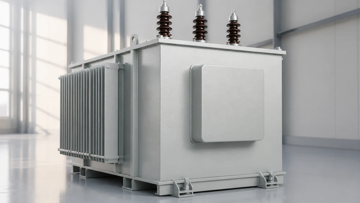
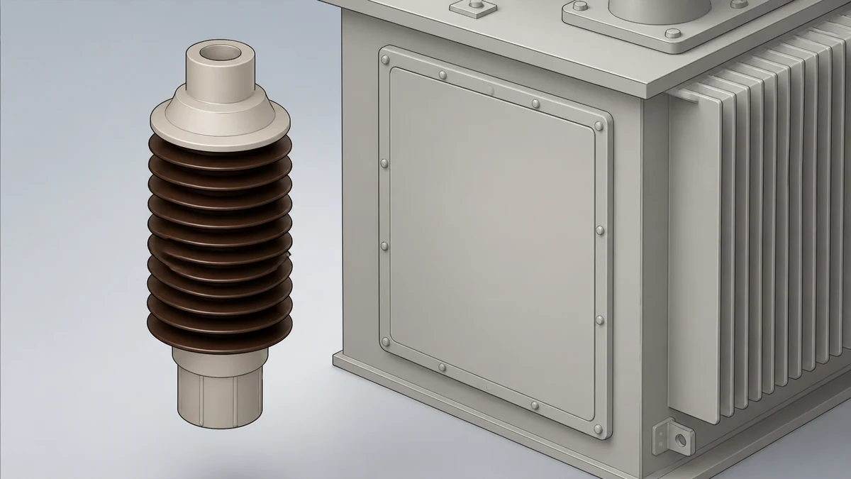
Preparing for transformer bushing gasket replacement means checking the whole sealing interface. This guide links flange drawings, gasket specifications, insulating-fluid compatibility, and the condition of both mating faces, so the outage package addresses damaged surfaces and missing installation information before parts are ordered.
Identify the installed bushing, flange drawing, approved gasket specification, and insulating medium before sourcing a seal.
Inspect both mating sealing faces for scratches, pitting, residue, and flatness concerns that a new gasket will not correct.
Plan surface preparation and assembly from the model-specific procedure; removed gasket dimensions alone do not establish the original seal profile.
Transformer bushing gasket replacement is not a parts-matching exercise — it is an interface-verification process that begins with the transformer's original design records and ends with a confirmed, manufacturer-approved seal assembly. No universal gasket material, profile, or torque value applies across bushing families; every replacement decision depends on the specific flange geometry, sealing face condition, and operating parameters of the unit in question. Treat any replacement that cannot be traced back to original-equipment documentation as unverified until those records are confirmed.
Why Gasket Integrity Is a System-Level Concern
A transformer bushing does more than carry conductor through the tank wall. It maintains the dielectric barrier between the energized conductor and the grounded tank, and the gasket at its base flange is the primary mechanical seal that keeps insulating oil or gas inside and moisture outside. A gasket failure at that interface is not a minor leak — it creates a direct pathway for moisture ingress into the insulating medium, which degrades dielectric strength and can precipitate partial discharge or thermal runaway well before any visible external sign appears.
The consequence is asymmetric: a correctly installed gasket is invisible in service, while a failed one can initiate a fault mode whose root cause is not obvious at the time of investigation. This asymmetry is why preparation, verification, and documentation carry more weight in bushing gasket work than the act of fitting the new part itself.
Insulated bushings for AC apparatus above 1 kV are governed by IEC 60137:2017, which establishes characteristics and test requirements for these components. What IEC 60137 does not establish is a universal gasket material choice, a field installation procedure, or interchangeability rules for a given transformer bushing interface. The standard defines what the assembled bushing must achieve; it leaves interface-specific sealing design to the equipment manufacturer. That division of responsibility is the first evidence boundary every procurement and maintenance team needs to internalize.
The Interface Is Equipment-Specific, Not Bushing-Family Generic
Bushing manufacturers offer selectable size, shape, and mounting configurations, as the Hitachi Energy overview of bushings for switchgear and breakers illustrates. The availability of options across a product family is precisely what makes appearance-based identification unreliable. Two bushings that look nearly identical — same voltage class, same general profile — can have different flange diameters, different sealing face finishes, different groove geometries, and different companion flange configurations on the transformer tank side.
An RFQ based on appearance or broad bushing family description alone is insufficient. The relevant drawing and original-equipment records must accompany any replacement request. This is not a procedural formality; it reflects the mechanical reality that a gasket seated in the wrong groove geometry, against a surface finished to a different specification, or compressed without the correct mating flange profile will not seal reliably regardless of material quality.
The companion flange on the transformer tank is equally part of the sealing system. Its surface finish, flatness tolerance, and any existing groove or land geometry must match the replacement gasket's design intent. A gasket sourced correctly for the bushing can still fail if the tank-side surface has corroded, been machined incorrectly during a prior service, or carries residue from an incompatible sealant applied previously.
Evidence Boundaries Before Any Replacement Decision
The following table maps the data categories required for a transformer bushing gasket replacement against what authoritative sources cover and what they explicitly leave to equipment-specific documentation.
Data Category
What IEC 60137 Covers
What It Leaves to Equipment Records
Bushing electrical performance
Withstand levels, partial discharge limits, temperature rise
—
Gasket material specification
—
Material type, hardness, chemical compatibility with insulating medium
Flange interface geometry
—
Groove dimensions, sealing face width, surface finish Ra value
Whether a replacement part fits a specific interface
Field installation
—
Governed entirely by model-specific approved manufacturer procedures
The practical implication: IEC 60137 compliance on a replacement bushing does not mean its gasket interface is compatible with a given transformer tank. Compliance and compatibility are separate verifications.
Sealing Surface Condition Assessment
The condition of both the bushing flange face and the tank companion flange determines whether a new gasket can seal correctly. A new gasket installed against a damaged or contaminated surface will replicate the failure mode of the original — sometimes faster, because the surface damage is now the limiting factor rather than gasket age.
Before any gasket is ordered, the sealing surfaces on both sides of the interface need direct inspection. Radial scratches or tool marks crossing the sealing land are the most common causes of leak paths through an otherwise correct assembly; circumferential marks from prior gasket removal are less critical but still need evaluation against the surface finish specification in the equipment records. Pitting from corrosion in the sealing zone requires a decision about whether the surface can be restored within specification or whether the flange itself needs attention before a replacement gasket will hold.
Residue from previously applied sealants or gasket material bonded to the flange face complicates new gasket seating. Removal methods and their compatibility with the flange material are specified in model-specific approved procedures — applying an incompatible solvent or an abrasive technique to a precision-finished flange surface can create the damage it is trying to remedy. Surface preparation that deviates from approved procedures is a common precursor to repeat failures.
Flatness across the sealing face matters proportionally to gasket stiffness. A harder gasket material requires a flatter, smoother mating surface to achieve uniform compression across the full circumference. Equipment records will specify the flatness and surface finish requirements; if measurement tools are not available on site, that gap in verification needs to be flagged before ordering replacement parts.
Identifying What You Actually Have
Accurate identification of the installed bushing is the prerequisite for everything else in this process. The nameplate data on the bushing itself is the starting point, but it is not always sufficient on its own. Bushings are sometimes replaced in service with non-original substitutions; nameplates can be damaged, illegible, or in older units, absent. The transformer's test records and original equipment documentation are the authoritative source, and they should be cross-referenced against the physical nameplate rather than assumed to match.
For the RFQ to be useful, the following must be confirmed from equipment records rather than visual assessment:
Bushing manufacturer, model designation, and voltage class
Flange outer diameter, bolt circle diameter, bolt count, and thread specification
Sealing groove dimensions and profile (if grooved), or sealing face width and surface finish (if flat-face)
Gasket material and hardness specification as supplied originally
Insulating medium in the transformer (mineral oil, ester fluid, SF₆, dry-type) because gasket chemical compatibility is medium-specific
Any prior modifications to the interface documented in service records
Visual measurement of a removed gasket is a useful cross-check but is not a substitute for original records. A gasket that has been in service has compressed, may have taken a permanent set, and could have swelled or shrunk depending on material and medium compatibility. Its measured dimensions after removal do not reliably represent the as-designed specification.
Installation and Failure Risk Factors
Gasket replacement carries several failure risk categories that are independent of gasket quality. Understanding them during the preparation phase allows the work package to be scoped correctly before the unit is taken out of service.
**Compression non-uniformity** is the most common cause of immediate or early post-replacement leaks. It results from an incorrect fastening sequence, a damaged or warped flange, or a gasket seated off-center. The correct sequence and method are governed by model-specific approved procedures and are not generalizable across bushing types or sizes.
**Material incompatibility with the insulating medium** produces failure over time rather than immediately. A gasket that seals correctly at installation can swell, harden, or lose mechanical integrity after weeks or months of contact with an incompatible fluid. Material approval must trace to the equipment manufacturer's specification for the specific insulating medium, not to general chemical compatibility charts for the material family.
**Surface contamination transfer** occurs when residue from cleaning agents, lubricants, or handling is introduced to the sealing zone. Some materials absorb contamination that then prevents uniform contact pressure even when the gasket appears correctly seated.
**Over-compression** from exceeding specified fastener loading can extrude the gasket beyond the sealing land, cause it to crack, or damage the flange face. Under-compression leaves the seal incomplete. Both outcomes are identical in consequence — a leak path — but their causes require different corrective actions. Fastener loading values and verification methods are specified in model-specific approved manufacturer procedures; they are outside the scope of preparation guidance.
For installation, surface preparation, torque sequences, and post-installation verification, model-specific approved procedures govern those actions exclusively.
Pre-RFQ and Pre-Outage Checklist
The items below consolidate the verification work that must be complete before a gasket replacement can be scoped, quoted, or scheduled. They are sequenced by dependency: items earlier in the list gate items that follow.
1. **Retrieve transformer original equipment documentation** — factory test records, as-built drawings, and bushing datasheet. Confirm bushing model and revision against the physical nameplate.
2. **Identify insulating medium** — confirm type and confirm no medium changes have occurred in service, since a medium change may have already exposed an incompatible gasket.
3. **Obtain bushing interface drawing** — flange geometry, sealing face or groove specification, surface finish Ra, and fastener specification. This drawing is the governing document for gasket sourcing.
4. **Inspect sealing surfaces before ordering** — document condition of bushing flange face and tank companion flange. Photograph any damage, residue, or non-conformance. Determine whether surface restoration is needed before replacement can succeed.
5. **Confirm gasket material specification from equipment records** — do not substitute based on material family or general chemical compatibility. The manufacturer's approved material is the specification.
6. **Check service history for prior non-standard repairs** — prior sealant applications, non-original replacement parts, or undocumented interface modifications may change what a correct replacement actually requires.
7. **Assemble RFQ data package** — bushing manufacturer, model, revision, flange drawing reference or confirmed dimensions, gasket material specification, insulating medium, and quantity. Include surface condition notes if restoration is needed.
8. **Confirm approved installation procedure availability** — model-specific approved procedures must be on hand before the outage begins, not sourced during the work window.
FAQ
What is the role of IEC 60137 in transformer bushing gasket replacement?
IEC 60137:2017 covers characteristics and test requirements for insulated bushings for AC apparatus above 1 kV. It defines electrical and thermal performance thresholds the assembled bushing must meet, but it does not establish gasket material choices, sealing interface geometry, field installation procedures, or interchangeability rules for a specific transformer. IEC 60137 compliance on a replacement bushing confirms it meets performance standards; it does not confirm its gasket interface is compatible with a given transformer tank flange.
What is the difference between bushing voltage class and interface compatibility?
Voltage class identifies the bushing's dielectric rating — the insulation level it is designed to withstand. Interface compatibility is a separate and independent property describing whether the bushing's physical flange geometry, sealing face dimensions, and surface finish match the transformer tank's companion flange. Two bushings with identical voltage class ratings can have entirely different flange interfaces. Sourcing based on voltage class alone without confirming interface geometry is a common cause of incorrect parts arriving on site.
What is the consequence of using a gasket material not specified by the manufacturer?
The primary consequence is medium incompatibility risk. Gasket materials that are not approved for the specific insulating fluid in service may swell, harden, or degrade at a rate that is not predictable from the initial installation. A material that seals correctly at commissioning can fail within months if it is chemically incompatible with the insulating medium. The secondary risk is compression behavior: different material formulations have different hardness and compression set characteristics, and a gasket that compresses differently than the design assumed will not achieve the intended sealing contact stress at the specified fastener loading.
What is the minimum documentation needed before issuing an RFQ for replacement gaskets?
The minimum package is the bushing manufacturer's designation and model, the interface drawing or confirmed flange dimensions (outer diameter, bolt circle, groove or sealing face geometry, surface finish specification), the gasket material specification from original equipment records, and the insulating medium type. Without the interface drawing or confirmed dimensions, a supplier cannot verify fit; without the material specification and medium type, chemical compatibility cannot be confirmed. Appearance-based or family-based descriptions alone are insufficient for a valid RFQ.
What is the risk of proceeding with gasket replacement before inspecting the sealing surfaces?
Installing a new gasket against an uninspected surface means the condition of the mating flange is unknown at the time of assembly. If the sealing surface has corrosion pitting, radial tool marks, residue from a prior sealant, or flatness deviation beyond the specification, the new gasket will not achieve the designed contact pressure distribution. The result is typically a leak at or shortly after return to service. The cost of the inspection — and of any surface remediation it identifies — is far lower than a repeat outage to address a failure caused by a known but uninspected surface condition.
LEO Chen
With more than 20 years of industry experience, LEO Chen has worked with major companies on switchgear, transformer components and medium-voltage equipment projects. He contributes practical guidance for engineers and sourcing teams, with a focus on clear selection criteria, application context and the information needed to prepare an informed RFQ. Connect with LEO on LinkedIn.