Send the request type, manufacturer, equipment model/year, part reference, ratings, quantity, destination, required date, and any drawing or photo notes. The SUVELL team will review the request.
Email: admin@suvell.com
Phone: +86 189 6871 1705
Factory: No.208 Wei 12 Rd, Yueqing Economic Development Zone, Wenzhou, Zhejiang, China
How to Read an Epoxy Insulator Drawing Without Assuming Interchangeability
An epoxy insulator drawing defines interfaces and operating requirements as well as shape. This guide walks through ratings, creepage, mounting tolerances, seals, and contact engagement, showing how a compatibility matrix exposes missing information before a visually similar component is accepted as a replacement.
Read the insulating outline, contact geometry, mounting features, and tolerances as separate checks; matching the outer envelope does not establish interchangeability.
Verify electrical and mechanical ratings alongside creepage, sealing details, orientation features, and the mating contact drawing.
Record each compatibility parameter as verified, failed, or unresolved, and identify the equipment-specific qualification evidence needed for substitution.
Reading an epoxy insulator drawing correctly means treating it as a system document, not a commodity spec sheet. A drawing encodes the insulating body's geometry, its connection role, and its mounting interface — all three must be verified against the target assembly before any replacement or procurement decision. Assuming that dimensional similarity between two drawings proves interchangeability is the single most common cause of field mismatches.
Why an Epoxy Insulator Drawing Is a System Document
An epoxy insulator does two jobs simultaneously: it isolates conductors at medium voltage, and it provides a structural and electrical connection path between compartments. ABB's documentation for the UniSec range describes epoxy-resin insulating bushings as including contacts that connect the circuit-breaker to the busbar compartment through a disconnector. That dual role — insulation and conduction — means the drawing must be read with both functions in mind at once.
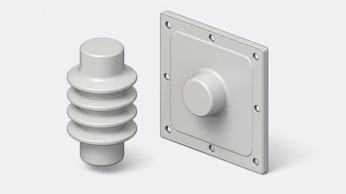
A drawing that shows only the insulating body's outer profile tells you less than half the story. The contact interface, the mounting flange geometry, the orientation of the conductor path through the body, and any embedded metallic inserts are equally load-bearing information. If any of those elements is read in isolation, a component that appears dimensionally close may still be electrically or mechanically incompatible.
The practical consequence: never reduce a drawing to its maximum outer diameter and overall length and call that a match. Those two numbers describe the envelope, not the function.
What the Drawing Sections Actually Encode
A well-structured epoxy insulator drawing separates at least four information layers, and each carries distinct verification obligations.
The **insulating body outline** gives the overall dimensions, material callout (typically cast epoxy resin, IEC or manufacturer grade), and any surface profile that affects creepage distance. Creepage is not the same as the physical length of the insulator: it follows the surface contour, and a shorter insulator with deep sheds may achieve greater creepage than a taller smooth-body version. Do not read the body length as a creepage proxy.
The **conductor or contact interface** specifies how current enters and exits the body. This may be a through-conductor, an embedded spade or tulip contact, or a bolted terminal pad. Hitachi Energy's bushing product documentation notes that size, shape, and mounting options are selectable — meaning these are not fixed commodity features but design choices that differ between manufacturer variants and customer specifications. Two bushings for nominally the same voltage class may have entirely different contact geometries.
The **mounting interface** defines how the component locates and seals against the switchgear panel or barrier. Bolt circle diameter, pilot diameter, sealing groove geometry, and orientation features (keyways, asymmetric bolt patterns) all appear here. A mismatch in any one of these makes physical installation impossible or creates a leak path in a gas- or fluid-insulated compartment.
The **tolerance and fit callouts** specify which dimensions are controlled tightly and which are reference-only. Drawing dimensions marked as reference (REF) or shown without tolerances are informational; they must not be used as acceptance criteria for a replacement part.
How IEC 62271-200 Bounds the Drawing Review
IEC 62271-200:2021 governs AC metal-enclosed switchgear and controlgear assemblies above 1 kV up to and including 52 kV at the assembly level. This scope boundary is decision-critical: the standard qualifies the complete equipment assembly through type testing, not individual components in isolation.
The implication for drawing review is direct. A component drawing reviewed outside its equipment context cannot be used as standalone proof that the component meets the tested performance of the original assembly. When a switchgear manufacturer's type test covers a specific internal configuration — including specific bushing geometry, creepage path, and contact interface — substituting a dimensionally similar component from a different source may technically void the assembly's compliance basis, even if the replacement passes its own component-level tests.
This is not a bureaucratic concern. It affects your actual liability and the asset's maintenance record. Before treating a drawing comparison as sufficient evidence for a replacement, confirm whether the switchgear OEM's service documentation or the relevant national authority requires re-verification after component substitution.
In practice, the drawing review is necessary but not sufficient. It establishes that a candidate part is plausibly compatible. Confirming compatibility requires tracing the part back to an approved source or a documented qualification test in the target assembly configuration.
Reading Voltage Class and Insulation Coordination on the Drawing
The drawing's title block or notes section typically carries voltage class markings: rated voltage (Ur), rated lightning impulse withstand voltage (Up), and rated power-frequency withstand voltage (Ud). These are not interchangeable labels. A component marked for Ur = 12 kV may carry a different Up than another 12 kV-class component if it was designed for a different insulation coordination level.
Do not assume that two components with the same Ur are interchangeable on insulation performance. Check that Up and Ud values on the candidate drawing match or exceed those of the original part, not just that the rated voltage class label is the same.
Creepage distance requirements vary by pollution degree and installation environment. IEC 60815 classifies pollution levels and specifies minimum specific creepage distances in mm/kV. If the drawing's specified creepage was sized for a pollution degree II indoor environment and the replacement will be installed in a coastal or industrial site classed at pollution degree III or IV, the original drawing specification is inadequate for the new site even if every dimension matches.
Interface Geometry: the Most Commonly Misread Section
The mounting and contact interface section of the drawing is where most field incompatibilities originate. The following parameters must be verified explicitly; none can be inferred from overall dimensions.
**Bolt circle and bolt count.** Even when two flanges have the same outer diameter, bolt circles frequently differ. A four-bolt pattern on a 90 mm pitch circle is not interchangeable with a four-bolt pattern on an 88 mm pitch circle even if the bolts are the same size.
**Pilot diameter and depth.** The pilot feature locates the bushing concentrically in its aperture. An incorrect pilot diameter produces either an interference fit that damages the sealing surface or a loose fit that allows movement under fault current forces.
**Orientation features.** Asymmetric bolt patterns, keyways, or flat faces on the flange control rotational orientation of the conductor path. Installing a bushing in the wrong rotational position places the internal contact geometry out of alignment with the connected equipment, which may prevent assembly entirely or create a contact interface with insufficient engagement depth.
**Sealing geometry.** In metal-enclosed switchgear, many bushing interfaces seal against SF6, nitrogen, or air at slight pressure differential. The O-ring groove dimensions — width, depth, and corner radii — must match the sealing ring specified for the original. Using a sealing ring in an undersized groove over-compresses the elastomer and accelerates its failure; an oversized groove allows the ring to move and leak.
None of these features is visible in a photograph or in a rendered 3D view. They exist only in the dimensioned drawing.
Connection Role: What the Drawing Does Not Show Directly
The ABB UniSec documentation identifies a specific functional role for epoxy bushings: they are the point through which the circuit-breaker connects to the busbar through a disconnector. This means the bushing is not simply a static feed-through — it participates in the switching and disconnecting sequence. The contact force, wipe, and engagement depth of the embedded contact are part of the switching performance.
A drawing that shows the bushing body in isolation does not show the mating contact geometry. To fully evaluate a replacement, you need the drawing of the mating interface — the tulip or plug contact on the circuit-breaker or disconnector side — and confirmation that the engagement depth and contact force specification are compatible.
When reviewing a drawing without access to the mating part drawing, this is the specific gap to flag in your procurement inquiry. Do not proceed on the assumption that standard tulip contacts are universally compatible; engagement depth tolerances and contact force are design-specific.
Thermal and Mechanical Load Data on the Drawing
Continuous current rating, short-circuit current rating (Ik), and peak current (Ip) may appear in the drawing title block or in a linked component specification. These ratings determine how the embedded conductor and its interface to the contact system are sized. An epoxy bushing rated for 630 A continuous has a smaller embedded conductor cross-section than one rated for 1250 A; the outer body dimensions may be identical.
If the drawing you are reviewing omits current ratings, do not assume the component is interchangeable with a higher-rated part. Request the full datasheet. This is a fundamental procurement step, not optional due diligence.
Mechanical load ratings — cantilever force, axial load, and torque — are equally relevant if the bushing supports busbars or cables that impose mechanical loads. Cast epoxy is strong in compression but can crack under sustained bending loads that exceed the design limit. The drawing may specify a maximum cantilever load; if it does, verify that the installed cable or busbar configuration stays within it.
Building the Verification Workflow
A structured review converts drawing interpretation into a documented decision. The following sequence applies to both replacement procurement and acceptance inspection of incoming parts.
Start with identity confirmation: verify that the manufacturer's part number, drawing revision, and date code on the physical component match the approved drawing. Many compatibility failures originate at this step — a superseded revision may look identical but carry changed dimensions.
Next, check rated electrical parameters in the title block against the switchgear's original specification: Ur, Up, Ud, and current ratings must all match or exceed originals.
Then review the insulating body: confirm material grade, overall dimensions within tolerance, creepage distance against site pollution class, and surface condition (no visible cracks, chips, or carbon tracking on incoming inspection).
Then review the mounting interface: bolt circle, bolt count, pilot diameter, sealing groove, and orientation features against the aperture drawing for the switchgear panel.
Then review the contact interface: confirm contact type, engagement depth dimension, and contact force specification against the mating part drawing.
Document the outcome as a compatibility matrix, not a narrative. Each parameter gets a pass, fail, or not-verified status. Anything marked not-verified must be resolved before a purchase order is placed.
What to Request Before Issuing an RFQ
An RFQ for an epoxy switchgear insulator that references only the overall dimensions and voltage class is underspecified and will attract responses for parts that may not be compatible. The following information set makes the inquiry unambiguous.
You need the original part number and drawing number with revision, the rated voltage (Ur), lightning impulse withstand (Up), power-frequency withstand (Ud), and continuous and short-time current ratings. Include the mounting interface drawing with tolerances, the contact geometry drawing or engagement specification, the creepage distance requirement with pollution class, and any OEM approval or qualification requirement from the switchgear manufacturer.
If the application is a gas-insulated or gas-assisted switchgear panel, add the sealing ring specification and the gas compatibility requirement for any lubricant or sealant applied to the bushing surface.
Specifying this information in the RFQ shifts the compatibility burden to the supplier, who must confirm in writing that their offered part meets each parameter. That confirmation becomes part of the procurement record and supports traceability if a warranty or compliance question arises later.
FAQ
What is an epoxy insulator drawing and what does it contain?
An epoxy insulator drawing is a dimensioned technical document that defines the geometry, electrical ratings, material specification, mounting interface, and contact interface of a cast-epoxy insulating component used in medium-voltage switchgear. It typically contains overall dimensions with tolerances, bolt circle and flange geometry, contact or conductor details, creepage distance, voltage and current ratings, and a material or grade callout. It does not contain information about the mating components or the assembled switchgear configuration; those must be sourced separately.
What is the difference between rated voltage and impulse withstand voltage on an insulator drawing?
Rated voltage (Ur) is the system voltage class the component is designed for — the continuous operating voltage under normal conditions. Impulse withstand voltage (Up) is the peak voltage the insulator must survive during a lightning impulse or switching surge without flashover or puncture. Two components with the same Ur can have different Up values if they were designed for different insulation coordination levels. Both must match the original specification; matching only Ur is insufficient.
What is creepage distance and why does it matter for drawing review?
Creepage distance is the shortest path along the insulator's outer surface between two conductive parts. It is measured following every contour of the surface profile, not as a straight-line dimension. It matters because contamination on the surface can form a conductive film, and a longer creepage path makes it harder for that film to sustain a leakage current or arc. The required creepage distance depends on the rated voltage and the site pollution class per IEC 60815. A drawing's specified creepage is valid only for the pollution class it was designed to; installations in more contaminated environments require a higher value.
What is the significance of the mounting interface drawing for switchgear bushings?
The mounting interface drawing defines how the bushing locates, seals, and fastens to the switchgear panel or barrier. It specifies the pilot diameter that centers the bushing in its aperture, the bolt circle that secures it, and the sealing groove geometry that prevents gas or moisture ingress. A bushing with a correct electrical specification but an incorrect mounting interface cannot be physically installed without modifying the panel, which would require OEM involvement and likely re-verification under IEC 62271-200. The mounting interface is therefore a hard compatibility gate, not a secondary consideration.
What is the role of IEC 62271-200 in evaluating component interchangeability?
IEC 62271-200:2021 covers AC metal-enclosed switchgear and controlgear assemblies from above 1 kV to 52 kV. Its type tests qualify the complete assembly, including all internal components in their specific configuration. A single component drawing reviewed in isolation cannot demonstrate compliance with this standard because the standard applies to the assembly as a whole. Substituting a component — even one that appears dimensionally identical — may require re-verification of the assembly if the switchgear manufacturer's documentation or the applicable authority identifies the component as part of the type-tested configuration.
LEO Chen
With more than 20 years of industry experience, LEO Chen has worked with major companies on switchgear, transformer components and medium-voltage equipment projects. He contributes practical guidance for engineers and sourcing teams, with a focus on clear selection criteria, application context and the information needed to prepare an informed RFQ. Connect with LEO on LinkedIn.