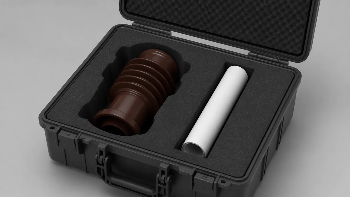
Send the request type, manufacturer, equipment model/year, part reference, ratings, quantity, destination, required date, and any drawing or photo notes. The SUVELL team will review the request.
Email: admin@suvell.com
Phone: +86 189 6871 1705
Factory: No.208 Wei 12 Rd, Yueqing Economic Development Zone, Wenzhou, Zhejiang, China
RMU Bushing Interface Measurements: A Field Measurement Sheet for Replacement Parts
A useful RMU bushing measurement sheet covers much more than overall height and diameter. Follow the mounting, retention, terminal, and contact dimensions needed for a replacement inquiry, and see how photographs, ratings, and original drawings help resolve compatibility questions that field measurements leave open.
Record flange and bore dimensions, retaining features, terminal geometry, and contact engagement depth, including the method used for each measurement.
Photograph the installed mounting and contact arrangement and capture the bushing or panel ratings and drawing reference.
Use field measurements to support the inquiry, then resolve tolerances, hidden contact details, and mating-part fit through drawing review.
Capturing the right dimensional and interface data before requesting a replacement RMU bushing is what separates a straightforward procurement from a weeks-long back-and-forth. A photograph and a nameplate reference are never enough: as Hitachi Energy's switchgear bushing documentation makes clear, size, shape, and mounting options can all be customized, so only a complete dimensional and interface evidence package can confirm replacement equivalence. Capture every measurement listed below, photograph the mounting arrangement, and retrieve the original drawing reference before issuing any RFQ.
Why a Photo and Part Number Are Not Sufficient Evidence
The temptation in the field is to photograph the existing bushing, note the OEM part number from the nameplate, and forward both to a supplier. This works only when the original part number remains active, the supplier holds the original drawing, and no undocumented field modification has occurred — three conditions that frequently do not hold simultaneously in aging RMU populations.
ABB's UniSec catalogue describes the epoxy-resin bushing as containing contacts that connect the circuit-breaker to the busbar compartment through the three-position disconnector. That functional description matters for replacement because the insulating body and the embedded contact geometry are both load-bearing elements of the interface. A bushing that matches the visible body dimensions but carries a different contact arrangement will not achieve correct circuit continuity. The insulating envelope and the electrical interface must both be verified independently.
Schneider Electric's PIX busbar-bushing installation documentation describes a mounting arrangement involving a bore-hole and retaining ring. The consequence for field measurement is direct: the mounting face geometry, the retaining ring groove position and diameter, and the bore-hole diameter are all distinct measurements that must be recorded. A general product family name — "PIX bushing" — does not resolve which variant is installed, because bore dimensions and retention arrangements can differ across generations of the same product family. The drawing reference stamped on the installation guide or visible on the switchgear's internal documentation label is the only authoritative tie between a physical assembly and the dimensional record.
This is the intent boundary that governs every section below: field measurements support quoting and preliminary selection. They do not replace drawing review. A supplier offering a replacement equivalent must confirm dimensional match against the original drawing, not against field measurements alone.
Functional Roles That Drive What You Must Measure
An RMU bushing performs two separable jobs, and each job generates its own set of critical dimensions.
The insulation function requires that the creepage and clearance distances of the replacement meet or exceed those of the original, which are set by the rated voltage of the switchgear rather than the bushing body size alone. Creepage distance is a surface measurement along the skirt profile. A bushing with a taller overall body but shallower skirt geometry can have less creepage than a physically smaller part. Record skirt count, skirt depth, and overall creep path length, not just overall body height.
The connection function, as described in ABB's UniSec documentation, means the bushing contains or interfaces with contacts that sit within the switchgear's disconnector circuit. Any contact socket or spigot embedded in the bushing must be dimensionally correct for the mating contact in the panel. Socket bore diameter, depth, and contact spring preload geometry are part of the interface — none of these are visible from outside the bushing once it is installed, which is why the original drawing reference is irreplaceable.
The Field Measurement Sheet
The measurements below constitute a complete field evidence package for a single bushing position. Capture all dimensions in millimeters. Record the measurement method alongside each value (vernier caliper, bore gauge, thread gauge, or visual estimation) so the supplier can assess confidence level.
**Mounting Flange and Panel Interface**
Record the outer diameter of the mounting flange and the bolt circle diameter. Count the bolt holes and record their diameter. Note whether the holes are through-drilled or threaded, and if threaded, record thread form and pitch with a thread gauge rather than estimating from a metric fastener handbook. Record the flange thickness and the surface finish condition (clean epoxy, corroded, or previously repaired with compound). If a retaining ring groove is present on the bore face, record the groove diameter and groove width — this is the dimension described in Schneider Electric's PIX installation documentation and cannot be omitted for that product family.
**Bore Dimensions**
Record the bore diameter at the panel face and, if accessible, at depth. Tapered bores require measurement at both ends. Note whether the bore surface shows evidence of a sealant or gasket compound, which would indicate a sealing requirement the replacement must also satisfy.
**Insulating Body**
Record overall height from mounting flange face to the top of the terminal. Record maximum outer diameter of the body and the diameter at the base of the first skirt above the flange. Record skirt count. Note whether the material surface shows UV degradation, tracking marks, or mechanical damage — these are condition notes for the asset record, not replacement dimensions, but they belong in the evidence package.
**Electrical Terminal**
At the high-voltage end, record the terminal type: threaded stud (record diameter and thread pitch), flat palm (record hole diameter and hole spacing), or plug-in socket (record socket bore and depth). At the panel-side contact end, record whether the contact is a fixed spigot, a spring-loaded pin, or a tulip-head socket, and record its diameter and the depth of engagement in the as-installed position.
**Rating Nameplate Data**
Record rated voltage (kV), rated current (A), rated short-time current and duration, and the drawing or type reference if legible. If the nameplate is missing or illegible, note that explicitly — a supplier cannot confirm equivalence without the rating data and will need to work from the switchgear panel's rating label instead.
Interface Dependencies That Are Not Visible on the Bushing Alone
Three installation dependencies regularly cause replacement failures that the bushing dimensions alone would not predict.
The panel-side contact alignment depends on the bushing seating depth. If the replacement bushing seats at a different depth — even by two or three millimeters — the spring-loaded or tulip-head contact inside the panel may not achieve correct engagement force. This is a kinematic constraint: the contact travel must bring the two mating surfaces into the designed overlap range. Record the distance from the mounting flange face to the panel-side contact tip, and confirm with the supplier that the replacement meets that dimension, not just the overall body length.
The retaining ring arrangement described in Schneider Electric's PIX documentation means that the panel bore and the bushing must both be dimensioned correctly for the ring to function. A replacement that is dimensionally correct everywhere except the groove will either not retain or will over-stress the epoxy body at the groove location. This is a case where the drawing reference is not optional — groove dimensions that look acceptable in the field may be at the tolerance boundary of the original specification, and only the drawing confirms whether the replacement groove will engage the same retaining ring.
Creepage and clearance requirements depend on altitude and pollution severity class, not just rated voltage. A direct replacement at a site with a higher pollution severity class than the original installation may require a longer creepage path than the standard part provides. If the asset has been relocated, or if environmental conditions have changed since original installation, verify that the replacement's creepage distance meets IEC 60815 for the actual site class.
Comparison: Measurement Evidence versus Drawing Evidence
Evidence type
What it confirms
What it cannot confirm
When it is sufficient
Field measurements
Body envelope, flange pattern, terminal type, rating nameplate
Contact geometry at depth, tolerance stack-up, material grade
Never alone; supports quoting and preliminary selection
OEM drawing
All dimensions and tolerances, material specification, contact geometry
As-installed condition, field modifications
Sufficient for new production or stock replacement if condition is verified separately
Both combined
Complete replacement equivalence
—
Required before committing to a replacement order
The table above reflects the position stated by Hitachi Energy's documentation: a photo, a legacy reference, or one nominal measurement alone cannot establish replacement equivalence. Two of the three columns in that table require a drawing. Field measurements move the process forward; they do not close it.
Verification Workflow Before Issuing an RFQ
Work through these steps in sequence. Each step either produces the next required input or reveals a gap that must be resolved before proceeding.
Locate the switchgear panel's internal documentation label or cabling compartment drawing pocket. Most medium-voltage RMU panels shipped after the mid-1990s carry a drawing reference on a label inside the low-voltage compartment. Record that reference before opening any high-voltage compartment.
Confirm isolation and earthing in accordance with the site's switching schedule. Measurement on a live or unearth bushing is a prohibited activity, not a procedural shortcut.
Execute the field measurement sheet in full. Do not omit any section because a dimension looks standard — standard dimensions vary between product families and generations.
Photograph the mounting face, the retaining arrangement, the panel-side contact in the as-installed position, and the nameplate. Four photographs minimum; more if the installation shows non-standard features.
Cross-reference the nameplate drawing reference against the supplier's document system before submitting the RFQ. If the drawing is available, the RFQ can be issued against the drawing number. If the drawing is not available, the field measurements and photographs become the primary specification, and the RFQ must explicitly state that the supplier is responsible for confirming dimensional compatibility.
Request a dimensional compliance statement from the supplier against the specific drawing or against the field measurement sheet. A general declaration of equivalent type is not sufficient.
Failure Risks Associated with Incomplete Measurement
Partial flash-over at the panel face is the most common consequence of a bushing that matches the body envelope but carries insufficient creepage for the installation environment. The degradation is progressive: surface tracking begins under contamination loading and may not be visible until a fault occurs.
Incorrect contact engagement depth produces either a high-resistance joint or intermittent contact during mechanical vibration. Both conditions present initially as thermal anomalies detectable by infrared survey before they progress to fault. A replacement bushing installed without verifying contact engagement depth will not be caught by routine visual inspection.
Retaining ring failure after an incorrect groove dimension causes the bushing to move under short-circuit mechanical force. The consequence is a panel fault from contact separation, not from insulation failure — which is why the fault mode may not be attributed to the bushing replacement without detailed investigation.
Each of these failure modes is avoidable if the corresponding dimension appears on the field measurement sheet and is confirmed against the replacement part's drawing before installation.
Completing the Evidence Package
A complete evidence package for a replacement RMU bushing contains: the completed field measurement sheet with all sections filled and measurement method noted, at minimum four photographs, the drawing reference from the panel documentation, and the switchgear panel's rated voltage and pollution severity class. Submit all four elements with the RFQ. A supplier receiving only part of this package should be expected to request the remainder before confirming equivalence — and a supplier who confirms equivalence without requesting it is taking a risk that belongs to the asset owner, not to the supplier.
Epoxy resin bushings for medium-voltage switchgear are manufactured to order in many configurations. Lead times for non-stock items can be significant. Initiating the measurement and drawing retrieval process before the bushing reaches end-of-life or fails is the operational decision that keeps outage windows manageable.
—
FAQ
What is RMU bushing dimensions measurement?
RMU bushing dimensions measurement is the process of capturing the complete set of physical interface parameters — flange geometry, bore diameter, body envelope, terminal type, contact engagement depth, and retaining arrangement — for a bushing installed in a ring main unit switchgear panel. The measurements are captured in the field against the installed part and used to support replacement part quoting and preliminary selection. They do not replace review of the original manufacturing drawing, which remains necessary to confirm tolerance compliance and contact geometry.
What is the minimum data needed before requesting a replacement bushing quotation?
The minimum useful evidence package is: all field measurements from the mounting flange, bore, insulating body, and terminal sections; the drawing or type reference from the panel nameplate; the switchgear rated voltage and current; and photographs of the mounting face and panel-side contact. A part number or photograph alone is not sufficient, because customized sizing and mounting options — as noted in Hitachi Energy's switchgear bushing documentation — mean that a type reference does not uniquely define all dimensions without the associated drawing.
What is the role of the drawing reference in confirming bushing equivalence?
The drawing reference ties the physical part to its complete dimensional specification, including tolerances, material grade, and contact geometry at depth. Field measurements capture nominal envelope dimensions but cannot resolve tolerance stack-up or the internal contact geometry described in ABB's UniSec documentation as the connection between the circuit-breaker and the busbar compartment. A replacement confirmed against the drawing reference carries a higher confidence of functional equivalence than one confirmed against field measurements alone.
What is the difference between creepage distance and clearance in bushing selection?
Creepage distance is the shortest path along the surface of the insulating body between two conductive parts. Clearance is the shortest path through air. Both are minimum values set by the rated voltage and the pollution severity class of the installation site, per IEC 60815. A bushing can meet the clearance requirement while failing the creepage requirement if its skirt geometry is insufficient for the site's contamination level. Replacing a bushing with one that has the same rated voltage but a different skirt profile may reduce creepage below the site requirement, increasing the risk of surface tracking under contaminated conditions.
What is the significance of the retaining ring arrangement for replacement compatibility?
As described in Schneider Electric's PIX busbar-bushing installation documentation, some RMU bushing mounting arrangements use a bore-hole and retaining ring to secure the bushing in the panel. The retaining ring groove on the bushing must match the ring dimensions and the panel bore exactly. A replacement bushing with incorrect groove position or width will either fail to retain under short-circuit mechanical forces or will apply stress to the epoxy body outside the designed load path. This dimension must appear on the field measurement sheet and be confirmed against the replacement drawing before installation.
LEO Chen
With more than 20 years of industry experience, LEO Chen has worked with major companies on switchgear, transformer components and medium-voltage equipment projects. He contributes practical guidance for engineers and sourcing teams, with a focus on clear selection criteria, application context and the information needed to prepare an informed RFQ. Connect with LEO on LinkedIn.