Send the request type, manufacturer, equipment model/year, part reference, ratings, quantity, destination, required date, and any drawing or photo notes. The SUVELL team will review the request.
Email: admin@suvell.com
Phone: +86 189 6871 1705
Factory: No.208 Wei 12 Rd, Yueqing Economic Development Zone, Wenzhou, Zhejiang, China
Off-Load Tap Changer Inspection: Position Indication, Contact Condition, and Oil Leakage
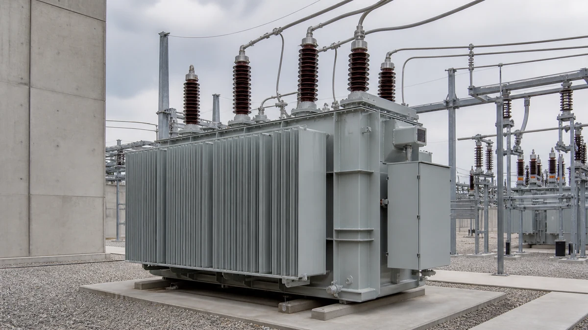
An off-load tap changer inspection links position indication, contact condition, and oil containment while the transformer is de-energized. Learn what to record before moving the selector, how winding resistance supports contact assessment, and which equipment details help define a replacement inquiry.
With the transformer de-energized, record the as-found tap position and check that the drive has fully engaged the indicated position.
Review accessible contact surfaces and winding resistance across tap positions against the installed model’s documentation.
Record oil level with ambient conditions, distinguish fresh leakage from old staining, and identify the mounting and drive arrangement before requesting replacement parts.
De-energized tap-changer inspection focuses on three physically observable conditions — position indication accuracy, contact surface condition, and oil containment integrity — each of which can be assessed without energizing the transformer. These checks establish a baseline before recommending service, and each finding must be interpreted against the specific tap-changer design; manufacturer documentation governs allowable limits, not cross-product benchmarks.
Why the Inspection Scope Boundary Matters
Off-load tap changers operate only with the transformer de-energized. That single constraint shapes every inspection decision. You cannot observe contact bounce, thermal signatures under load, or dielectric recovery in service; you can only evaluate what is mechanically and visually accessible during a planned outage. Any inspection method or acceptance criterion that requires the unit to be energized or under load is outside the scope of a de-energized inspection and should not be borrowed from on-load tap-changer literature.
The same boundary applies to published manufacturer data. Reinhausen's operating instructions for the DEETAP SPTM describe de-energized tap-changer monitoring as occasional visual inspection and include model-specific inspection items in a structured inspection plan. Those intervals and action thresholds are documented for that design. Transferring them to a different off-load tap-changer model is not supported by that documentation and may produce either unsafe under-inspection or unnecessary intervention on a different design. The practical rule: use the manufacturer's own inspection plan for the unit under review, and treat any cross-referenced interval as a starting orientation only.
Position Indication: What It Confirms and Where It Can Mislead
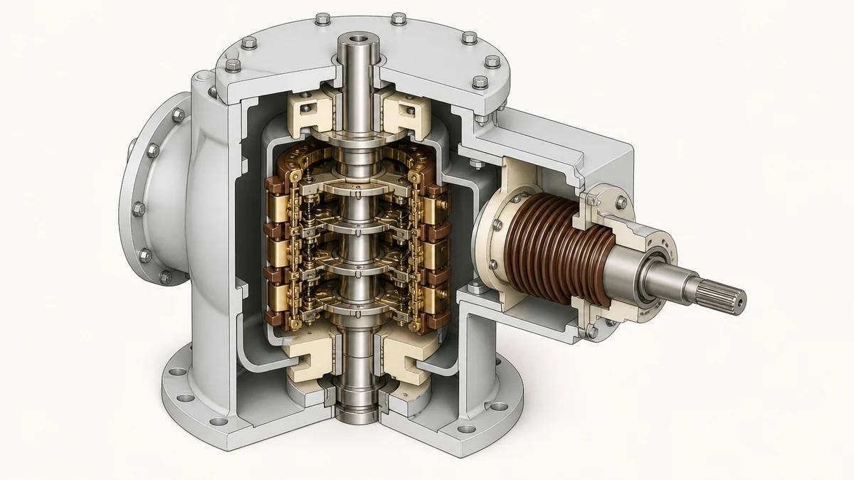
A position indicator shows the tap selected on the external drive mechanism. What it does not directly confirm is whether the internal contact assembly has landed on the corresponding tap position. Mechanical looseness, drive linkage wear, or an incomplete operating cycle can leave the indicator showing a tap number while the internal contacts rest between positions or against a different tap contact.
Before any electrical test or return-to-service, verify that the external indicator reading corresponds to a fully engaged drive position, not an intermediate stop. For spring-assisted or detented designs, this means confirming that the mechanism has completed its travel to the next detent, not merely that the indicator needle has moved. An indicator that stops at a non-integer position — or one whose mechanical feel is soft rather than firm at the detent — should be investigated before the transformer is energized.
Record the indicator reading in the equipment record for every inspection. If the as-found reading differs from the last recorded position without a documented switching operation, investigate the cause before proceeding. Position drift in a locked-out transformer can indicate unauthorized operation, indicator decoupling, or drive mechanism movement under thermal cycling.
Position indicators on oil-immersed tap changers sometimes have a secondary check: the selector switch position can be confirmed by measuring resistance between tap terminals. A resistance value consistent with the expected tap ratio supports — but does not replace — the mechanical indicator check, because a floating contact can produce an intermediate resistance that is numerically close to the target.
Contact Condition: Accessible Evidence and Its Limits
Contact condition assessment on an off-load tap changer is constrained by access. For externally accessible selector switches, visual inspection of the contact surfaces can reveal pitting, carbonization, or silver migration. For internally mounted contacts in an oil-filled compartment, contact condition is inferred from indirect evidence: dissolved gas analysis of the oil, winding resistance measurements across each tap position, and the history of switching operations since the last service.
Pitting and erosion are normal over time on switching contacts; the question for inspection is whether the remaining material is within the manufacturer's serviceable range. Because that range is design-specific, a general visual impression of "significant erosion" is not a sufficient basis for a replacement recommendation without a dimensional or functional reference from the manufacturer's service documentation. Record what you observe, photograph contact surfaces if accessible, and cross-reference with any wear limit stated in the maintenance manual for that tap-changer model.
Winding resistance measurements taken across all tap positions provide the most actionable indirect evidence during a de-energized inspection. A resistance value that is significantly higher on one tap than the surrounding taps, or that is erratic on repeated measurement at the same tap, indicates a high-resistance contact joint. This finding warrants further investigation before return to service: it could reflect contact surface contamination, inadequate contact force, or material loss that is not visible from outside the compartment.
Carbon tracking on the selector is a different failure mode from contact erosion. Carbon deposits on insulating surfaces between taps reduce creepage distance and can initiate surface tracking under voltage. If carbon is visible on the insulating substrate between positions — not just on the contact faces themselves — the dielectric condition of the selector assembly needs to be evaluated, not just the contact metal.
Oil Leakage: Indication as Evidence, Not Diagnosis
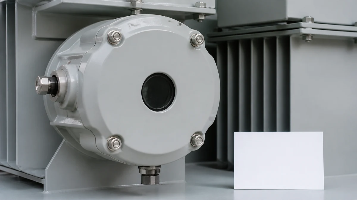
Oil-filled tap-changer compartments use liquid-level indicators to provide visible confirmation that the insulating oil is within the designed operating range. Hitachi Energy identifies liquid-level indication as a feature of oil-filled transformer and tap-changer equipment, with visible indication supporting the equipment record. That framing is precise: the indicator tells you a level exists; it does not tell you what caused a level change or what service action follows from it.
A low liquid-level reading on the indicator has multiple possible causes: normal thermal contraction at low ambient temperature, evaporation losses through a slow seep, a sudden leak from a gasket or fitting, or oil transfer between compartments in certain designs. Each cause has a different urgency and a different corrective path. Logging the indicator reading against ambient temperature and comparing it to the previous record is the first diagnostic step. A level that is consistently low across a temperature range — rather than low only at cold ambient — is more likely to indicate actual oil loss.
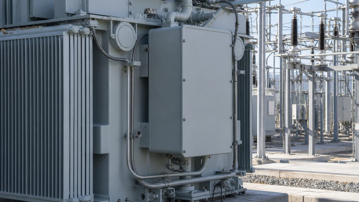
External evidence of leakage — oil staining on the tap-changer housing, around bushings, at drain plugs, or along gasket lines — should be documented with photographs and location notes. Staining alone does not confirm an active leak: transformer equipment can retain surface residue from factory testing, previous maintenance, or historic seepage that has since self-sealed. The relevant finding is whether staining is fresh (wet, soft edges, consistent color) versus aged (dry, hardened, discolored). If fresh staining is present, identify the source before returning the unit to service.
Gasket condition at the tap-changer to tank interface and at any inspection covers deserves explicit attention. Nitrile and neoprene gaskets compress and take a set over time, and a gasket that sealed adequately for years may leak after a cover is opened and re-torqued, particularly if it has been re-used across multiple inspections. The decision to replace a gasket at inspection is generally lower-cost than an unplanned outage for a leak that develops after reassembly.
Oil condition should also be sampled during any inspection that involves opening the tap-changer compartment. Dissolved gas analysis and dielectric strength testing of the tap-changer oil are performed separately from the main tank, because the tap-changer compartment can accumulate gases from contact arcing even in a de-energized design where arcing is infrequent. A degraded dielectric reading or unexplained gas content in a compartment with no recent switching history is a finding that warrants investigation into whether the compartment has been contaminated or whether unintended switching has occurred.
Inspection Workflow: Sequencing the Three Checks
Sequencing the three inspection areas reduces the risk of overlooking an interaction between them. A practical sequence for a de-energized off-load tap-changer inspection runs as follows:
Start with the oil-level indicator before opening anything. Record the as-found level and compare it to the previous log entry. Check for external staining and classify it as fresh or aged. This establishes whether the oil compartment is intact before any covers are disturbed.
Verify position indication next, while the unit is still in its as-found state. Record the as-found indicator position, confirm it against the last documented switching record, and check the mechanical feel at the detent. Do not operate the selector until the as-found position is recorded.
Proceed to contact condition assessment after the position check. For externally accessible contacts, inspect visually and photograph any surface anomaly. For internally inaccessible contacts, collect winding resistance data across all taps before disassembly. If the inspection plan calls for opening the compartment, do so after oil samples are drawn so the sample is representative of the undisturbed condition.
Reassemble with new gaskets at any joint that was broken, torque to the manufacturer's specification, and verify oil level after refill before closing out the inspection record.
Data to Gather Before a Replacement or RFQ Decision
A tap-changer replacement or major refurbishment decision should not rest on a single inspection finding. The data set that supports a defensible decision includes: the as-found winding resistance values for all tap positions, the oil dielectric strength and dissolved gas analysis from the tap-changer compartment, a photographic record of contact surfaces if accessible, the indicator reading history across at least the last two inspections, and the total number of tap operations since the last service (from a switching counter if installed, or from the equipment record).
When contacting a supplier for a replacement unit or service parts, the minimum information required to specify correctly includes the transformer nameplate data (kVA, voltage ratings, impedance), the tap-changer manufacturer and model designation, the number of tap positions and the voltage step per tap, the phase configuration, and whether the existing unit is a separate oil compartment design or shares oil with the main tank. An RFQ that omits the model designation or phase configuration cannot be filled accurately, and a replacement unit ordered on voltage and kVA data alone may not be mechanically compatible with the existing drive mechanism or mounting arrangement.
FAQ
What is an off-load tap changer inspection?
An off-load tap changer inspection is a de-energized examination of the tap-changer mechanism, contact assembly, position indicator, and oil containment system, performed while the transformer is isolated from the network. It establishes whether the tap-changer is fit for continued service or requires maintenance before the next operating cycle.
What is the difference between position indication and contact confirmation?
Position indication shows the tap selected by the external drive mechanism. Contact confirmation — verified through winding resistance measurement — checks whether the internal contact has actually landed and made electrical connection at the corresponding tap. The two can disagree if the drive linkage has wear, if the mechanism stopped short of full travel, or if the indicator has become decoupled from the selector shaft.
What is the significance of fresh oil staining on a tap-changer housing?
Fresh oil staining — wet, with soft edges and consistent color — indicates an active or recent leak from a fitting, gasket, or weld seam. It must be distinguished from aged residue, which is dry and may reflect historic seepage that is no longer active. Fresh staining requires source identification and correction before the unit returns to service; aged staining should be documented but does not by itself prevent energization.
What is the role of dissolved gas analysis in a tap-changer inspection?
Dissolved gas analysis of the tap-changer compartment oil identifies gases associated with thermal degradation or arcing within that compartment. Because the tap-changer oil is separate from the main tank in many designs, it must be sampled independently. Unexpected gas content in a compartment with a low switching count is a diagnostic finding, not a maintenance interval trigger; it indicates a condition that needs investigation before the cause can be established.
What is required before submitting an RFQ for a replacement off-load tap changer?
The minimum data set for a replacement RFQ includes the transformer nameplate ratings, the tap-changer manufacturer and model number, the number of tap positions and voltage step per position, the phase configuration, and whether the tap-changer uses a separate oil compartment or shares oil with the main tank. Mechanical interface details — mounting dimensions and drive shaft configuration — are needed to confirm compatibility with the existing installation.
LEO Chen
With more than 20 years of industry experience, LEO Chen has worked with major companies on switchgear, transformer components and medium-voltage equipment projects. He contributes practical guidance for engineers and sourcing teams, with a focus on clear selection criteria, application context and the information needed to prepare an informed RFQ. Connect with LEO on LinkedIn.