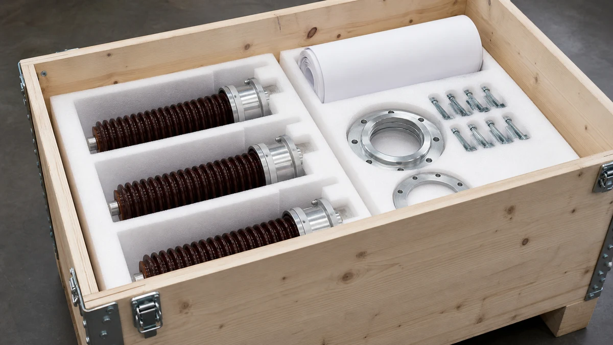
Send the request type, manufacturer, equipment model/year, part reference, ratings, quantity, destination, required date, and any drawing or photo notes. The SUVELL team will review the request.
Email: admin@suvell.com
Phone: +86 189 6871 1705
Factory: No.208 Wei 12 Rd, Yueqing Economic Development Zone, Wenzhou, Zhejiang, China
Transformer Bushing Leakage, Overheating, and Surface Damage: When to Investigate Replacement
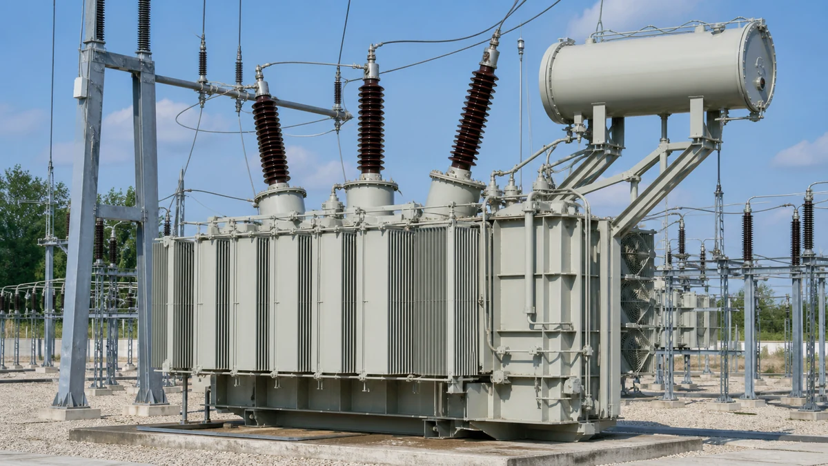
Oil staining, hot spots, and surface damage require different checks depending on transformer bushing construction. This guide connects leakage location and thermal findings with electrical test trends, then identifies the dimensional, terminal, and fluid-compatibility information needed to investigate a replacement.
Identify the bushing construction and trace oil staining to its source before interpreting leakage or a low oil level.
Assess terminal heating, body heating, cracks, and tracking alongside power factor and capacitance trends, with load and ambient conditions recorded.
Prepare flange, conductor, terminal, and insulating-fluid details when assessment findings lead to a replacement inquiry.
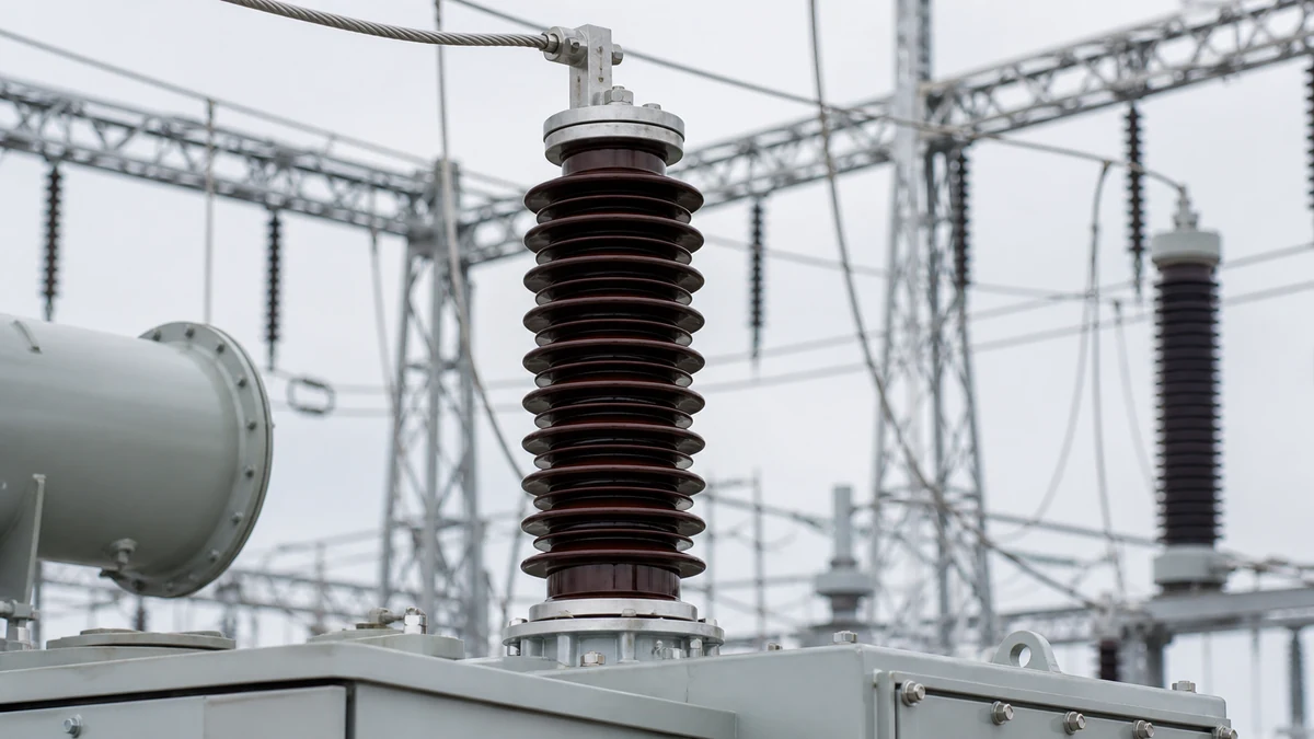
Visible oil staining, abnormal infrared signatures, or surface tracking on a transformer bushing are not automatic replacement triggers — they are signals that warrant structured evidence gathering before any asset decision. Whether any one sign justifies replacement depends on bushing construction, service history, power factor trend, and the consequence of unplanned failure at that specific installation. The decision belongs to a qualified assessment process, not a visual threshold alone.
How Bushing Construction Shapes What Fails and How
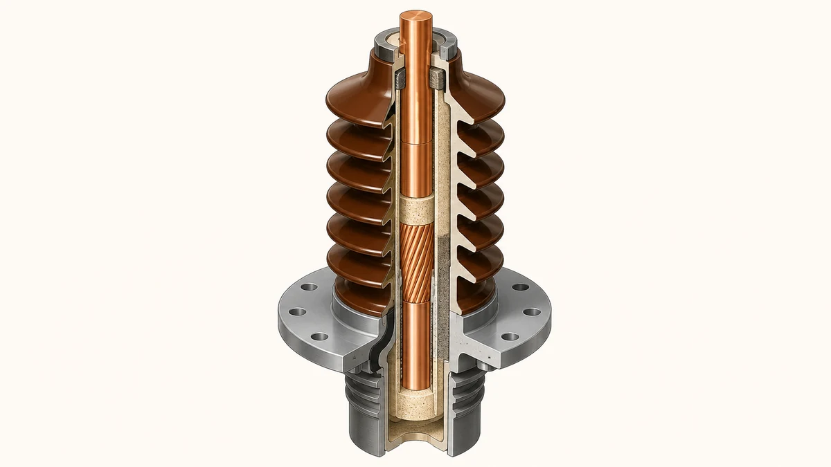
Understanding which failure modes apply to a given unit requires knowing its construction first. The most common types in service are oil-impregnated paper (OIP), resin-impregnated paper (RIP), resin-bonded paper (RBP), and capacitor bushings with dry or gas-filled designs. Qualitrol's guidance on bushing monitoring distinguishes these constructions because their dielectric systems degrade through different mechanisms and respond differently to the same environmental or electrical stress.
OIP bushings rely on oil-paper insulation and carry an oil reservoir that is visible and monitorable. A low or absent oil level in that reservoir changes the dielectric behavior of the bushing immediately — it is not just a maintenance note. RIP and RBP bushings are sealed and do not have an accessible oil system, which removes one failure pathway but also removes a key visual condition indicator. Capacitance-graded bushings — the dominant design in HV and EHV equipment — use a layered foil-paper construction to distribute electrical stress radially. Damage to any grading layer shifts the voltage distribution and elevates stress on adjacent layers, creating a progressive failure mechanism that is invisible to surface inspection.
The practical implication: a surface inspection strategy that is adequate for one construction may miss the dominant failure mode of another. Selecting the right assessment methods requires identifying the installed construction from nameplate and procurement records before deciding what evidence to collect.
What Leakage Actually Indicates
Oil leakage from a bushing can originate from several distinct locations, and the location determines the urgency and the appropriate response.
Leakage at the top terminal or cap assembly typically indicates a gasket or seal failure at a mechanical interface. This is often a maintenance item, but if the bushing is OIP and oil level has dropped as a result, the dielectric system is already compromised. Leakage along the porcelain or polymer skirt surface is more serious: it may indicate a crack in the insulator body, a failed cement joint, or internal pressurization from dielectric decomposition gases. Leakage at the transformer tank flange interface usually points to the mounting gasket rather than the bushing body itself, but oil contamination spreading from that joint can obscure other signs and complicate infrared reading.
The critical distinction is whether leakage has caused a change in oil level in an OIP bushing. Hitachi Energy's condition assessment guidance includes oil level — where applicable — as a discrete assessment input alongside thermal data and electrical test results. A sealed bushing showing surface staining from an external source looks similar to one that has been slowly weeping from an internal seal failure. Confirming which is present requires physical inspection of the suspected origin point, not remote observation alone.
Overheating: Reading an Infrared Image Correctly
Thermal anomalies detected by infrared inspection require interpretation before they become action items. A hot spot on a bushing image is a location finding, not a diagnosis.
The most common legitimate thermal signatures on a bushing are: elevated temperature at the top terminal due to a loose connection or inadequate contact area; distributed heating along the body due to increased dielectric losses as power factor degrades; and localized hot spots associated with partial discharge activity within the insulation system. These are mechanically and electrically distinct failure modes that produce visually similar infrared images.
Hitachi Energy's service guidance identifies thermal and electrical stress, along with power factor and capacitance, as relevant condition-assessment inputs considered together — not as independent triggers evaluated in isolation. This matters operationally: an elevated terminal temperature may be resolved by a torque check and connector cleaning, while elevated body temperature combined with a rising power factor trend points toward internal insulation deterioration that no mechanical adjustment will address. Acting on infrared data alone, without supporting electrical test data, risks either over-responding to a benign connection issue or under-responding to a genuine insulation problem.
Ambient conditions affect the baseline for any thermal comparison. Infrared readings taken in direct sunlight, at significantly different load levels, or across different ambient temperatures are not directly comparable. A reliable infrared assessment uses multiple readings over time under consistent conditions, or normalizes for load and ambient before drawing a trend conclusion.
Surface Damage and Tracking: Distinguishing Cosmetic from Structural
The porcelain or polymer housing of a bushing is both the mechanical support and part of the insulation system. Not all surface damage is structurally equivalent.
Chalking and superficial discoloration on silicone rubber sheds are normal aging effects and do not indicate insulation compromise. Loss of hydrophobicity — the property that causes silicone rubber to bead water and resist surface tracking — is more significant. A surface that has lost hydrophobicity in a contaminated or coastal environment will accumulate a conductive film under wet conditions, which drives leakage currents and initiates tracking. This is detectable with a visual water spray test and is recoverable with cleaning and, in some cases, surface treatment, but it requires attention before carbonized tracking channels form.
Deep tracking — visible as darkened, carbonized paths along the shed profile — represents permanent surface damage. Tracking channels provide a low-resistance path that concentrates subsequent leakage current, accelerating further damage. Once tracking channels reach a threshold depth or length, they are not restorable by cleaning; the housing's insulation integrity is structurally reduced. The threshold for replacement versus continued monitoring in a tracked bushing depends on the depth and continuity of the channels, the contamination class of the site, and the availability of regular inspection. A tracked bushing that is cleaned and returned to service in a high-pollution environment without a monitoring plan is a predictable failure in progress.
Porcelain cracks, even hairline, carry different implications than polymer surface damage. A cracked porcelain body can allow moisture ingress into the insulation system of an OIP bushing, directly accelerating internal degradation. Any confirmed crack in the porcelain housing of an OIP bushing is a priority assessment item, not a watch-and-see finding.
Electrical Test Data: What It Tells You That Inspection Cannot
Visual and thermal inspection can identify surface conditions and connection quality. They cannot characterize the state of the internal insulation system. Power factor and capacitance testing close that gap.
Power factor (or dissipation factor, tan δ) measures dielectric losses in the insulation system. A rising power factor indicates that the insulation is absorbing more energy per cycle — a sign of moisture ingress, contamination, or thermal degradation of the oil-paper system. Capacitance measurement detects changes in the effective dielectric geometry of a capacitance-graded bushing. A significant change in capacitance from the nameplate value, or from a previous test, indicates that the grading layer structure has been altered — either through a shorted foil layer or a physical disruption of the winding geometry.
Hitachi Energy's assessment framework identifies power factor and capacitance as explicit condition inputs, which reflects their practical diagnostic value: they provide evidence about internal insulation state that cannot be inferred from any external observation. The reference baseline matters significantly. A single power factor reading evaluated against a generic table is less informative than the same reading evaluated against the factory test value and a prior field measurement trend. Bushings without documented test history require more conservative interpretation of absolute values.
IEEE C57.19.100 and IEC 60137 both provide test procedures and guidance values for bushing condition assessment. Neither standard provides a universal replacement trigger at a single numeric threshold; they provide the test methodology and context for qualified interpretation. Where trending is available, a rate-of-change in power factor is often more actionable than any single absolute value.
The Role of Ambient and Installation Conditions
A bushing operating at the same electrical load can be under very different stress depending on where and how it is installed.
Altitude reduces air density, which lowers the dielectric strength of the external air gap around the bushing. Bushings are rated for standard altitude (typically 1,000 m or below) and require uprated clearances or insulation at higher elevations. Coastal and industrial installations with high salt or chemical contamination drive surface tracking and leakage current at a rate that inland clean-air installations do not experience. Hitachi Energy's condition assessment guidance includes ambient conditions as an assessment consideration because the same bushing condition has a different failure risk profile depending on the operating environment.
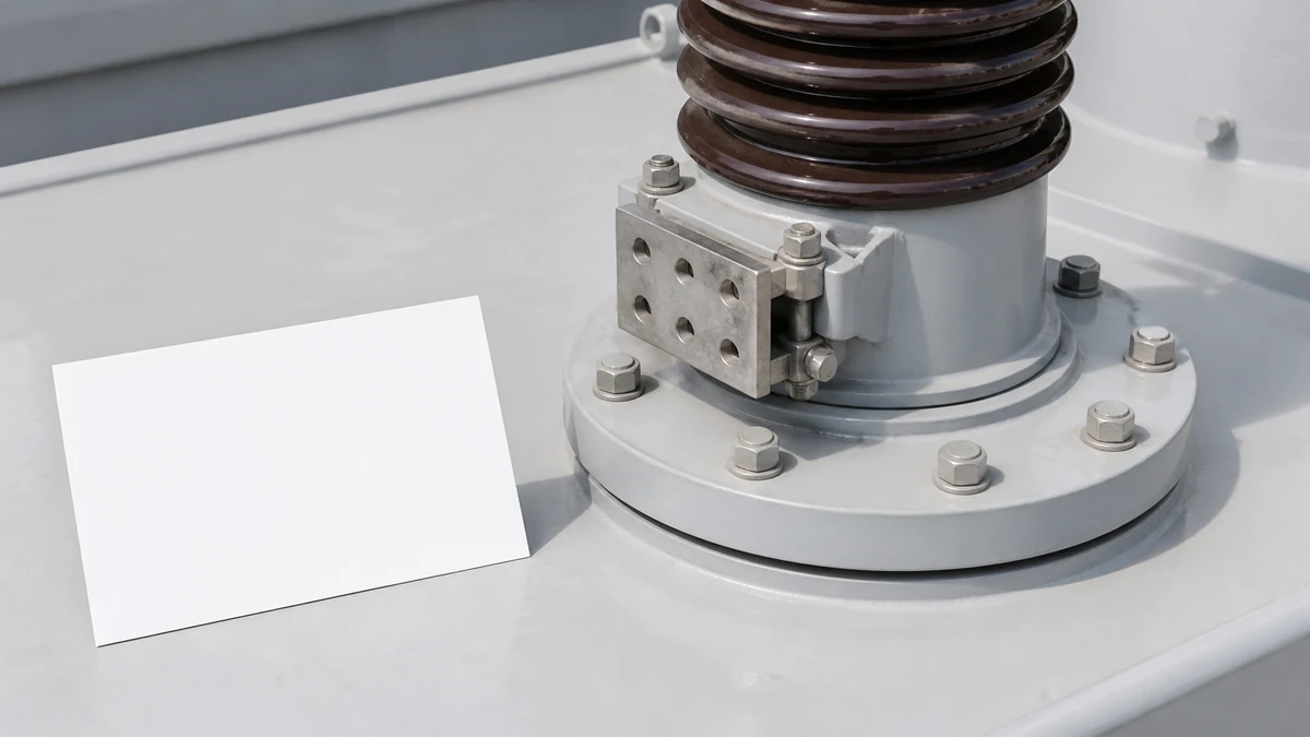
Top-terminal condition is separately listed in Hitachi Energy's assessment framework because terminal degradation — corrosion, loose hardware, inadequate contact area — drives thermal stress at the point of maximum mechanical and electrical load on the external interface. A terminal showing active corrosion in a high-humidity or coastal environment represents a degradation pathway that is independent of the bushing's internal condition and may require action on a shorter timeline.
Installation geometry also affects assessment. A bushing mounted at a non-standard angle may trap air in an OIP design, creating an oil gap above the conductor tube. This is an installation-specific risk that visual inspection of the bushing body alone will not reveal; it requires knowledge of the mounting angle limits specified by the manufacturer.
When Assessment Escalates to Replacement Investigation
No single sign reviewed above constitutes a standalone replacement decision. The escalation logic is cumulative and asset-specific.
A reasonable escalation framework looks like this: a single anomalous visual finding initiates more frequent monitoring and, if the bushing construction permits, a scheduled electrical test. Two or more concurrent anomalies — for example, an infrared hot spot combined with a power factor reading above the manufacturer's or IEEE C57.19.100 guidance value — shift the recommendation toward active replacement planning rather than monitoring extension. A confirmed cracked porcelain body on an OIP bushing, tracking channels that span more than a fraction of the creepage distance, or a sudden significant shift in capacitance from baseline are individually sufficient to accelerate the timeline for a qualified engineering review.
Hitachi Energy frames condition assessment and replacement as asset-specific service decisions, not generic triggers — reflecting the reality that identical external symptoms in two bushings may represent very different risk levels based on service history, construction, test data trend, and operating environment. The replacement decision is the output of that structured process, not an input.
Data to Assemble Before an RFQ or Replacement Decision
When assessment evidence supports moving toward replacement, the quality of the specification work determines whether the replacement bushing performs equivalently. The following data points are required before a meaningful replacement inquiry:
**Bushing identification:** Nameplate voltage class, BIL rating, current rating, manufacturer, model or type designation, and mounting configuration (draw-lead, rod, or fixed). For capacitor bushings, the rated capacitance and tan δ from the factory test report.
**Physical interface:** Flange dimensions and bolt pattern, overall length and mounting height, top-terminal type and hardware specification, and — for draw-lead designs — the internal conductor diameter and connector type at both ends.
**Oil compatibility:** For OIP bushings on oil-filled equipment, the transformer's insulating fluid type (mineral oil, FR3, silicone) affects bushing specification, since not all bushing seals and insulation systems are compatible with all fluid types.
**Standards compliance requirements:** Whether the installation requires IEC 60137, IEEE C57.19.00 / C57.19.01, or both, and whether a specific test protocol or third-party witness test is required by the asset owner or utility standard.
**Service history and failure mode:** Any available test data history, the specific signs that triggered replacement investigation, and the failure mode if the bushing has already failed, because a replacement into the same service condition without addressing the root cause restores risk rather than eliminating it.
A replacement bushing that matches voltage and current class but mismatches flange geometry, conductor interface, or fluid compatibility introduces installation risk. Dimensional and interface verification against the existing equipment drawing is a prerequisite, not an optional step.
FAQ
What is a transformer bushing failure sign that warrants immediate escalation?
A sudden measurable shift in capacitance from baseline, a confirmed crack in a porcelain OIP bushing body, or complete oil loss from an OIP reservoir are conditions that warrant immediate engineering review rather than continued monitoring. Each represents a change in the bushing's fundamental insulation or mechanical integrity, not a trend to be tracked. Heavily carbonized tracking channels spanning a significant portion of creepage length are similarly an escalation item, particularly on equipment in contaminated service environments.
What is the difference between power factor trending and a single power factor reading for bushing assessment?
A single power factor reading tells you where the bushing is today relative to a reference value. Trending — comparing sequential readings over the bushing's service history — tells you the rate of change, which is more actionable for planning. A bushing at 0.5% power factor that has risen from 0.2% in two years is a different risk profile from a bushing that has been stable at 0.5% for a decade. IEEE C57.19.100 supports trend-based interpretation as the preferred approach when historical test records are available.
What is the role of capacitance measurement in bushing condition assessment?
Capacitance measurement detects changes in the dielectric geometry of a capacitance-graded bushing — specifically, whether any of the grading foil layers have been shorted or physically disrupted. The nameplate capacitance value is the reference. A field measurement that deviates significantly from that reference, or from a prior field measurement, indicates internal structural change that requires engineering evaluation. Capacitance change and power factor change are complementary — power factor tracks loss increase while capacitance tracks geometric change — so both are included in formal assessment protocols.
What is hydrophobicity and why does it matter for polymer bushing condition?
Hydrophobicity is the property of silicone rubber shed materials that causes water to bead and roll off the surface rather than forming a continuous conductive film. It is not permanent: UV exposure, surface contamination, and mechanical stress degrade it over time. A bushing that has lost hydrophobicity in a contaminated or coastal environment becomes susceptible to leakage current along the shed profile under wet conditions, which initiates tracking. Silicone rubber can recover hydrophobicity after a period of rest or cleaning, but once carbonized tracking channels have formed the surface damage is permanent and the assessment shifts toward structural evaluation of the shed integrity.
What is the significance of top-terminal condition in a bushing assessment?
The top terminal is the mechanical and electrical interface between the external conductor and the bushing, and it carries the full line current at the bushing's rated value. Loose, corroded, or undersized hardware at this interface increases contact resistance, which produces localized heating detectable by infrared. Hitachi Energy identifies top-terminal condition as a discrete assessment input because terminal degradation is mechanically independent from internal insulation condition — a bushing can have good dielectric test values and a failing terminal, or vice versa. Both must be assessed, because either can produce a service failure.
LEO Chen
With more than 20 years of industry experience, LEO Chen has worked with major companies on switchgear, transformer components and medium-voltage equipment projects. He contributes practical guidance for engineers and sourcing teams, with a focus on clear selection criteria, application context and the information needed to prepare an informed RFQ. Connect with LEO on LinkedIn.