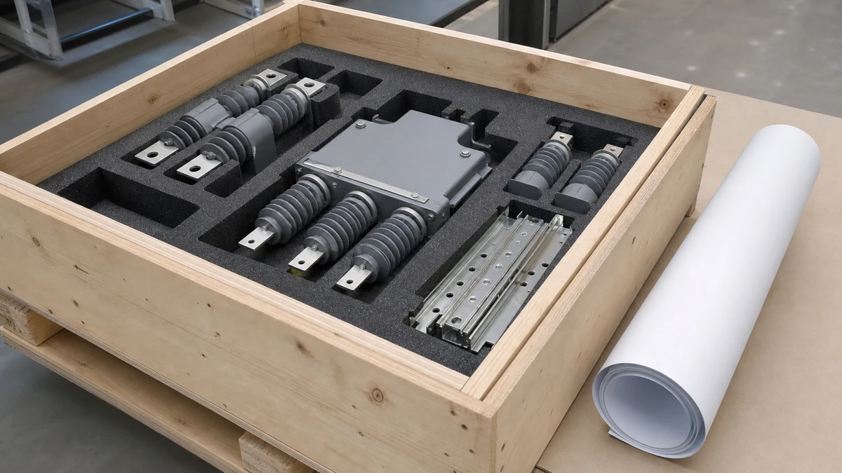
Send the request type, manufacturer, equipment model/year, part reference, ratings, quantity, destination, required date, and any drawing or photo notes. The SUVELL team will review the request.
Email: admin@suvell.com
Phone: +86 189 6871 1705
Factory: No.208 Wei 12 Rd, Yueqing Economic Development Zone, Wenzhou, Zhejiang, China
Vacuum Circuit Breaker Racking and Interlock Inspection Checklist
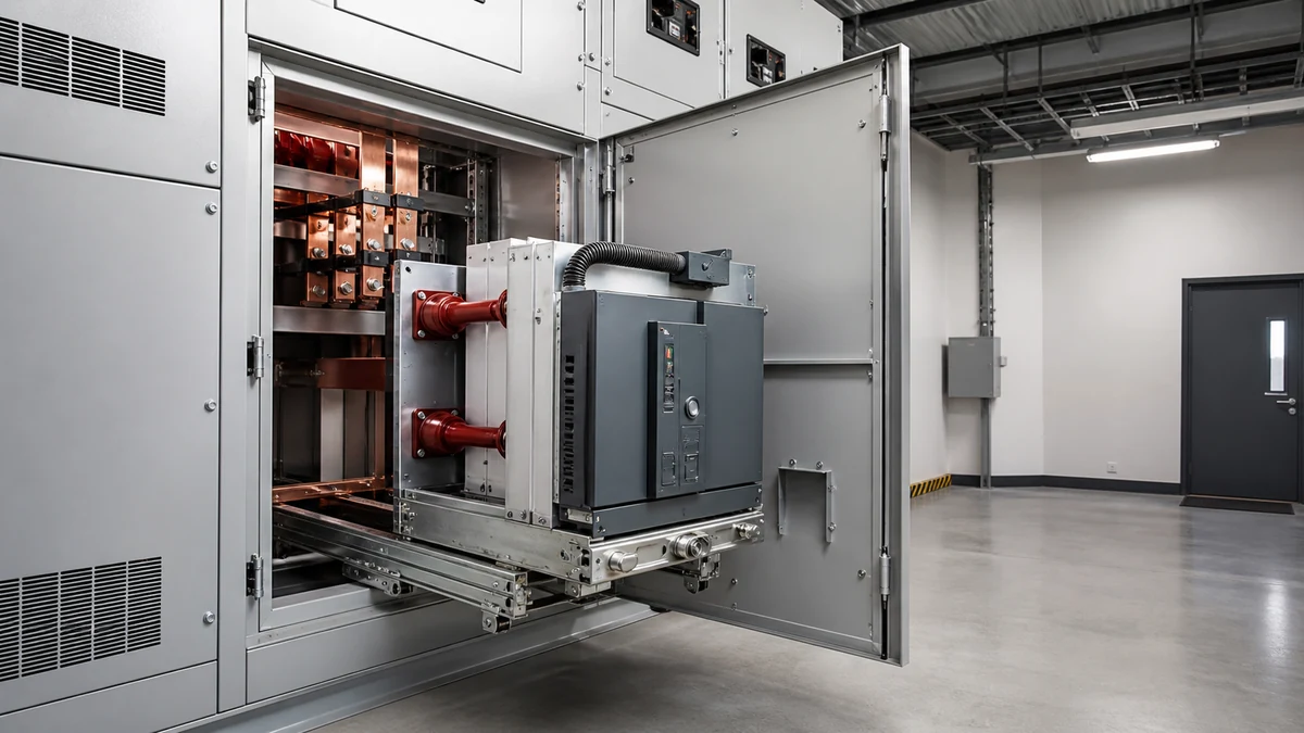
A drawout vacuum circuit breaker inspection must address the racking path, position indication, and interlocks as well as visible pole and compartment condition. This checklist organizes those checks around the installed OEM procedure and distinguishes visual observations from vacuum-integrity and contact-wear assessments.
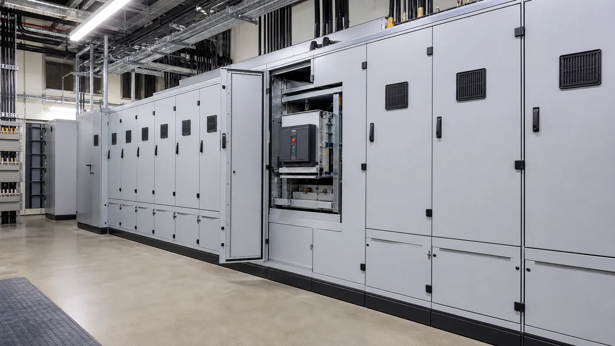
Use the installed breaker and switchgear manuals to review cradle rails, racking drive, travel stops, and position indication under the approved isolated inspection procedure.
Check racking and closing interlock functions separately, including mechanical linkages and electromagnetic devices where fitted, and record each result against the model’s permitted states.
Inspect pole exteriors, shunts, primary contacts, and shutters, while keeping vacuum integrity and contact-wear assessment within the OEM’s specified test procedures.
A de-energized vacuum circuit breaker racking inspection verifies that the mechanical racking mechanism, interlock system, and vacuum interrupter poles are all in acceptable condition before the breaker is returned to service. Skipping or abbreviating this inspection introduces two compounding risks: an undetected interlock fault can allow racking movement in a prohibited state, and a degraded vacuum interrupter can fail to interrupt fault current even when the breaker operates correctly. The checklist below organizes those verification steps by logical phase; each item maps to a specific failure mode rather than a generic safety requirement.
Pre-Inspection Setup and Documentation Requirements
Confirm the following before touching any mechanism:
**Work order and OEM documentation available.** The racking sequence, interlock logic, and permitted indicator positions are model-specific. Schneider Electric's EvoPacT MV guide and ABB's Vmax/A IOM manual both identify their interlock designs as equipment-specific — what blocks racking in one design may not correspond to the same indicator position in another. Obtain the exact manual revision for the installed switchgear before interpreting any position indicator.
**Electrical isolation and LOTO complete.** Bus, cable, and control power must be confirmed de-energized and locked out. Verify that auxiliary control voltage to the closing coil is isolated; the interlock inspection specifically requires moving the breaker between positions, which must occur with zero stored closing energy unless the procedure explicitly states otherwise.
**Earthing verified.** Confirm that the upstream bus and cable compartment are earthed per site procedure before opening the circuit breaker compartment.
**Baseline condition recorded.** Note the as-found position of the breaker (connected, test, disconnected, or intermediate), the as-found state of every visible interlock flag or indicator, and any abnormal sounds, odors, or mechanical resistance encountered on arrival. This record is the comparison baseline for post-inspection sign-off.
Do not proceed if any prerequisite is unresolved. An incomplete LOTO or missing OEM documentation is a stop-work condition, not a risk to accept.
Racking Mechanism Visual and Mechanical Inspection
Racking Cradle and Travel Path
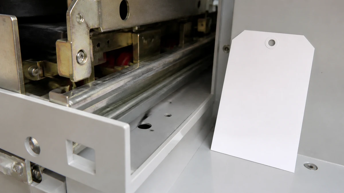
Inspect the cradle rails and guide channels for debris, corrosion, scoring, or deformation. Debris accumulation is the most common cause of increased racking force; scoring indicates misalignment or prior forced movement.
Check that the racking screw or worm-gear assembly shows no cracked threads, stripped drive surfaces, or excessive backlash. Backlash greater than approximately one thread pitch warrants further measurement against the OEM service limit.
Verify that the racking handle drive coupling engages cleanly and fully seats before applying force. A partially seated coupling transmits torque unevenly and can shear drive pins.
Confirm that the breaker moves freely by hand through the full travel range without binding, skipping, or requiring asymmetric force. Binding at a specific point in travel often corresponds to a cam lobe or interlock plunger that is worn, misaligned, or loaded with contamination.
Position Indicator and Travel Stops
Verify that the position indicator (mechanical flag, graduated scale, or panel window) advances smoothly and reaches the correct terminal marking at each nominal position: disconnected, test, and connected. An indicator that stops short of the terminal marking suggests the breaker has not fully reached that position, which leaves primary disconnects partially engaged — a high-resistance and potentially arcing condition under load.
Inspect mechanical travel stops for deformation or missing hardware. A missing stop allows overtravel into the compartment structure.
With the breaker at each nominal position, attempt to continue racking in the same direction. The stop must arrest travel with no perceptible flex in the mechanism.
Lubrication Assessment
Check the racking screw, cradle slides, and pivot points against the OEM lubrication specification. Dried or contaminated grease increases racking force and can cause interlock cams to stick in the blocked position, falsely preventing authorized racking movement.
Do not apply lubricant without identifying the OEM-specified type. Incorrect lubricant — particularly silicone-based products applied to surfaces specified for mineral grease — can migrate to contact surfaces and degrade contact resistance.
Interlock System Inspection
The interlock subsystem on medium-voltage draw-out switchgear serves two distinct protective functions: it prevents the breaker from being racked while closed (avoiding primary disconnect arcing), and it prevents the breaker from being closed while in an intermediate racking position (avoiding connection at partial engagement). These two functions may be implemented in the same or separate mechanisms depending on the design.
ABB's Vmax/A IOM manual describes racking interlocks that prevent movement or closing in particular states for its design; the exact positions and sequences are model-specific and must be confirmed against the installed switchgear documentation before performing any functional test. Schneider Electric's EvoPacT MV guide similarly identifies an electromagnetic interlock that can block the racking mechanism as an equipment-specific maintenance item. Neither manufacturer's guidance creates a transferable adjustment procedure — what follows applies the inspection logic, not any model-specific setting.
Mechanical Interlock Inspection Items
Inspect all interlock cams, levers, plungers, and pins for wear, cracking, deformation, or corrosion. Pay particular attention to the cam lobe surfaces that engage the racking-block plunger; a worn lobe radius reduces the blocking force margin.
Verify that interlock springs return each blocking component to the nominal rest position promptly when released. A sluggish return indicates worn or contaminated springs and is a precursor to interlock defeat under vibration.
Confirm that the mechanical racking block engages positively when the breaker is in the closed position, and that it releases fully when the breaker is open. Record the as-found condition of the closed-position indicator and the block engagement as a matched pair — a mismatch between reported position and block engagement is a fault condition requiring investigation before return to service.
Check all interlock linkages for loose fasteners, missing cotter pins, and elongated holes. Mechanical interlock reliability is a fastener-level detail; a single missing retaining pin can allow the linkage to skip.
– Schneider Electric's EvoPacT MV guide identifies an electromagnetic interlock that can block the racking mechanism as an equipment-specific maintenance item. Where fitted, verify that:
– The solenoid or coil assembly is physically secure and shows no signs of overheating (discoloration, deformed insulation, burnt odor).
– Control wiring to the interlock is intact, correctly routed, and shows no chafing against the racking mechanism travel path.
– The interlock releases and engages correctly in response to the control signal — with control power applied per OEM procedure, confirm the block retracts fully; with control power removed or the signal absent, confirm the block re-engages fully.
– Do not attempt to adjust the electromagnetic interlock travel or coil gap without OEM service data for the specific model. Coil gap affects both pull-in force and the operating voltage threshold.
Functional Interlock Test Sequence
Perform this test only with LOTO confirmed and closing energy absent:
1. Place breaker in the open position and confirm the racking block is disengaged. Attempt to rack from disconnected toward connected; movement should be permitted.
2. Place breaker in the closed position (mechanically, without energizing). Confirm the racking block engages. Attempt to rack; movement must be prevented. Record the force or resistance observed — forced movement under this condition is a critical finding.
3. Open the breaker and confirm the block disengages. Resume racking to connected; movement should be permitted.
4. At each nominal position, attempt to close the breaker. At intermediate positions, the closing interlock must prevent the close command from reaching the closing coil or mechanically block the close latch.
Record pass or fail for each step against the specific interlock mechanism tested (mechanical, electromagnetic, or both). Do not aggregate to a single pass/fail without identifying which mechanism was exercised.
Vacuum Interrupter Pole Inspection
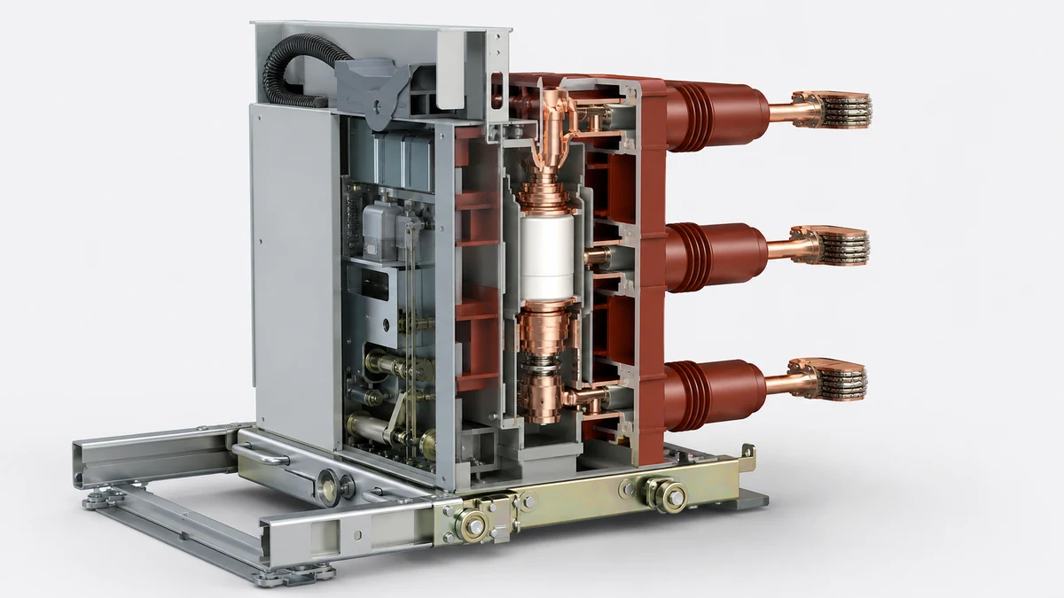
Schneider Electric's EvoPacT MV guide identifies inspection of vacuum interrupter poles as an equipment-specific maintenance item. The inspection items below cover the observable condition of the interrupter assembly on a de-energized, racked-out breaker; they do not include contact wear measurement or vacuum integrity testing, which require OEM-specified tooling and procedures.
Inspect the exterior of each interrupter bottle for cracks, chips, surface tracking, carbonization, or arc damage on the ceramic or epoxy insulating body. Any visible surface tracking is a disqualifying condition — the interrupter must be replaced before return to service.
Inspect the flexible shunt connections and braided conductors at each terminal for broken strands, overheating signs, or loose mechanical terminations. A broken shunt strand reduces the current-carrying path and increases terminal temperature under load.
Check upper and lower terminal clamp bolts for correct torque where accessible without disturbing the assembly. Verify against the OEM torque specification, not a generic class-based value, because vacuum interrupter terminal connections have specific torque limits to avoid cracking the ceramic body.
Inspect the operating rod and insulating coupling between the interrupter and the operating mechanism for cracks, elongated holes, or signs of mechanical overload. A cracked insulating coupling creates a partial discharge initiation site.
Verify that all three poles show consistent external appearance. Asymmetry in discoloration, surface condition, or mechanical wear between poles warrants investigation before return to service, as it may indicate that one phase has been carrying disproportionate fault energy.
**What this inspection does not replace:** Vacuum integrity requires a vacuum test or a contact resistance trending comparison over time; neither can be done visually. Contact erosion requires a feeler gauge or OEM-specified contact wear gauge. If the inspection history shows the breaker has operated through multiple fault interruptions since the last contact measurement, schedule that measurement before returning the breaker to service even if the visual inspection is clean.
Arc Flash and Compartment Condition Assessment
Inspect the primary disconnecting contact fingers on both the breaker and the fixed contacts in the compartment for pitting, erosion, overheating (blue-black discoloration), or deformation. Contact erosion increases connection resistance; severe pitting may require contact replacement.
Check the compartment interior surfaces — shutters, barriers, and insulating panels — for carbon deposits, tracking, or arc damage. Carbon deposits on insulating surfaces are conductive and reduce the effective creepage distance.
Verify that arc chutes (where fitted) are intact and correctly seated. A displaced arc chute can redirect arc products toward adjacent components or personnel during a subsequent fault.
Confirm that all compartment barriers and shutters operate correctly, return to the closed position under spring action, and are not deformed or held open by debris.
Post-Inspection Checklist and Return-to-Service Criteria
All of the following must be confirmed before re-energization:
Item
Required Condition
LOTO removal
Per site de-isolation procedure, verified by authorized personnel
Racking mechanism
Moves freely through full travel; no binding; stops firm
Position indicator
Matches actual position at all three nominal points
Mechanical interlock
Blocks racking when breaker closed; releases fully when open
Electromagnetic interlock (if fitted)
Engages and releases correctly with control power per OEM
Closing interlock
Prevents close command at all intermediate positions
Vacuum interrupter poles
No visible cracks, tracking, or arc damage on any of three poles
Shunt connections
No broken strands; terminations secure
Primary contacts
No severe pitting or deformation; within OEM wear limits
Compartment barriers and shutters
Intact, seated, operating correctly
Lubrication
Applied per OEM specification where required
Documentation
All findings recorded; deviations dispositioned or flagged for follow-up
Any item marked as a finding that has not been dispositioned per OEM guidance is a hold point. Do not authorize return to service against an open finding without a documented engineering decision.
Application Notes for the VS1 Vacuum Circuit Breaker
The VS1 is a draw-out indoor vacuum circuit breaker in the 12 kV class. Its racking mechanism, interlock design, and vacuum interrupter pole configuration follow the general design conventions described in this checklist, but the specific indicator positions, interlock engagement points, racking torque limits, and contact wear limits are defined in the VS1 product documentation. Apply this checklist in conjunction with that documentation, not as a substitute for it. Where the VS1 documentation specifies a different inspection sequence or a model-specific adjustment procedure, the product documentation governs.
FAQ
What is vacuum circuit breaker racking inspection?
Vacuum circuit breaker racking inspection is a de-energized maintenance procedure that verifies the physical and functional condition of the draw-out mechanism, interlock system, and vacuum interrupter poles before the breaker is returned to service. It confirms that the breaker can be safely moved between positions and will interrupt correctly once connected.
What is the purpose of the racking interlock on a medium-voltage breaker?
The racking interlock prevents two unsafe conditions: racking a closed breaker (which would force the primary contacts to separate under load, causing an arc at the disconnects) and closing a breaker that is not fully engaged at a nominal position (which would connect a circuit through partially made contacts). These are mechanically and electrically distinct failure modes, and the interlock system addresses both.
What does a failed interlock functional test indicate?
A failed racking interlock test — where the mechanism moves or allows a close command when it should be blocked — indicates that the blocking component is worn, misaligned, contaminated, or missing hardware. It is a critical finding that requires investigation and resolution before the breaker is returned to service. The failure mode determines whether the remedy is cleaning and lubrication, component replacement, or a more detailed OEM service procedure.
What is the difference between a mechanical and electromagnetic racking interlock?
A mechanical racking interlock uses a cam, lever, or pin driven by the breaker's own open/closed position to physically block the racking drive. An electromagnetic interlock, such as the type identified in Schneider Electric's EvoPacT MV guide, uses a solenoid energized by a control signal to engage or release a blocking plunger. Electromagnetic interlocks can be integrated into more complex key exchange or permissive systems, but they introduce a dependency on control power availability and wiring integrity that mechanical interlocks do not share.
What is contact erosion and why does it matter for vacuum interrupters?
Contact erosion is the gradual reduction in contact surface material caused by arcing during each interruption event. In a vacuum interrupter, the contacts operate inside a sealed evacuated bottle, and the erosion products are not visible externally. As contacts erode, the contact gap at the open position decreases, eventually reducing the dielectric withstand capability of the interrupter. Measuring contact wear requires a contact wear gauge applied per OEM procedure; it cannot be assessed visually and is not replaced by a clean exterior inspection.
What is the significance of asymmetric condition across the three vacuum interrupter poles?
Asymmetry in discoloration, surface deposits, or mechanical wear between the three poles suggests that one phase has interrupted significantly more energy than the others, or that one interrupter has a mechanical issue affecting its contact motion. Asymmetric interruption increases the probability of a restrike on the more heavily loaded phase. If asymmetry is observed, trending the contact wear on all three poles and comparing against fault event records is the appropriate next step before return to service.
LEO Chen
With more than 20 years of industry experience, LEO Chen has worked with major companies on switchgear, transformer components and medium-voltage equipment projects. He contributes practical guidance for engineers and sourcing teams, with a focus on clear selection criteria, application context and the information needed to prepare an informed RFQ. Connect with LEO on LinkedIn.