Send the request type, manufacturer, equipment model/year, part reference, ratings, quantity, destination, required date, and any drawing or photo notes. The SUVELL team will review the request.
Email: admin@suvell.com
Phone: +86 189 6871 1705
Factory: No.208 Wei 12 Rd, Yueqing Economic Development Zone, Wenzhou, Zhejiang, China
MV Switchgear Insulator Contamination: What to Inspect Before Re-Energizing
Contaminated MV switchgear needs more than a surface cleaning before a return-to-service decision. This guide covers deposit and discharge evidence, creepage-path inspection, OEM-specific cleaning, and insulation measurement records, with escalation points for damage or unresolved findings that require qualified technical assessment.
After approved isolation, document deposit coverage, moisture, tracking, discoloration, cracks, and concealed contamination along insulation surfaces before cleaning.
Use cleaning methods and electrical-test interpretation from the installed equipment’s OEM instructions, recording environmental conditions when comparing insulation measurements.
Resolve discharge damage, unexplained cracks, and abnormal test findings through qualified assessment before the authorized return-to-service decision.
Before re-energizing any medium-voltage switchgear after a contamination event, the inspection must confirm that the insulation system can withstand normal and transient operating voltages without tracking, flashover, or puncture. The evidence baseline comes from the equipment-specific OEM instruction book — not generic cleaning guides or cross-manufacturer tables — because contamination tolerance and acceptable condition limits are insulation-material and design-specific. Escalation to an OEM field service engineer or a certified testing contractor is the correct path when findings exceed what the instruction book treats as field-maintainable.
Why Contamination on MV Insulators Is a Distinct Failure Mode
Contamination does not simply lower the surface resistance of an insulator. It creates a conductive film that redistributes voltage stress across the insulation surface. When leakage current flows through that film, localized dry bands form where resistivity is higher. Voltage concentrates across those bands. If the electric field across a dry band exceeds the local breakdown strength, a partial discharge arc bridges it. Repeated arcing degrades the insulation surface through a process called tracking — the progressive carbonization of an organic or hybrid insulation material that lowers its surface resistance further and extends the conductive path toward the ground electrode or an adjacent phase.
The endpoint of uncontrolled tracking is a flashover, a phase-to-ground or phase-to-phase fault with enough energy to cause equipment destruction, arc flash injury, and an extended outage. The mechanism is relevant to inspection because it explains what you are actually looking for: not just contamination deposits as a cosmetic finding, but any evidence that the deposit has already initiated tracking activity.
Contamination sources matter because they determine the deposit's conductivity and adhesion. Salt fog and coastal marine air deposits are highly conductive when wetted. Industrial particulates, including cement dust, carbon soot, and metalite fines, vary in conductivity but tend to be adhesive. Combined deposits — where a hygroscopic industrial dust absorbs moisture — produce the highest surface conductivity. Biological contamination such as bird fouling introduces conductive organic material that is also mechanically aggressive on some surface coatings.
The insulation material determines how the surface responds. Epoxy resin components, used widely in MV switchgear for bus support, spout insulators, and barrier systems, have good bulk dielectric strength but their surfaces can track if the formulation does not include adequate arc-resistant fillers. Cast resin, glass-reinforced polymer, and glazed porcelain each have different surface energy, adhesion characteristics, and tolerance to partial discharge activity. Inspection severity and escalation thresholds are therefore specific to the insulation type installed in the equipment under review.
Establishing the Required Safety State Before Any Inspection
No contamination inspection begins until the equipment has been isolated, de-energized, grounded, and locked out under the applicable energy isolation procedure. This is not a routine disclaimer — it is operationally significant because contaminated insulators in a partially re-energized bay can flash over at applied voltages below normal operating voltage, particularly when surface contamination is wet. Schneider Electric's Masterclad maintenance instructions treat contamination as an inspection item only after the required safety state has been established, which means the inspection sequence is subordinate to the lockout/tagout process, not parallel to it.
Confirm grounding at each point of potential re-energization. Verify that adjacent bays or cable circuits that share a bus or are coupled through capacitive grading do not present a hazard. Where contamination has affected cable terminations or bushing interfaces, the inspection perimeter extends to those components.
Document the date and conditions of the contamination event before beginning the inspection. Knowing whether the equipment was energized during the event, whether the deposit was wet at the time of exposure, and whether any visible arcing, tripping, or alarming occurred shapes the inspection focus. Evidence of in-service partial discharge or flashover changes the escalation path immediately.
Visual Inspection: What to Look for Surface by Surface
Visual inspection is the first and most informative step. It must be systematic and documented, not a quick sweep before cleaning.
**Tracking marks and carbonization.** ABB's padmount switchgear instruction book explicitly identifies tracking as a primary inspection finding. Tracking presents as a dendritic or linear carbonized path along the insulation surface, typically progressing from a high-stress point such as an electrode edge, a screen termination, or a fitting edge toward a lower-potential surface. Even a partial or early-stage track is a meaningful finding because it confirms that the contamination has already driven surface discharge activity. Tracking on epoxy surfaces is generally irreversible; the carbonized material cannot be fully removed without mechanical reduction of the surface, and even after mechanical treatment, the surface has lower resistance to future tracking.
**Streaked discoloration.** ABB's inspection guidance also identifies streaked discoloration as a specific inspection item. Streaking differs from uniform surface staining: it indicates that leakage current has preferentially flowed along one path, concentrating surface heating and chemical degradation in a line. Whitish or yellowish streaks on epoxy indicate electrothermal degradation of the resin surface. Dark streaks suggest carbonization. Either is an escalation trigger.
**Cracks.** Surface cracks and bulk cracks are separate concerns. A hairline surface crack on a contaminated insulator provides a capillary path for conductive moisture to penetrate, effectively extending the conductive film into the bulk of the insulation and dramatically shortening the discharge path. ABB's inspection criteria include cracks as a specific finding to manage under equipment-specific instructions. Any crack on an HV-stressed surface, regardless of whether contamination is present, requires documentation and assessment.
**Contamination deposit character.** Record the deposit coverage (partial or complete), thickness, color, and texture. Thin, uniform deposits are different from thick, hygroscopic crusts. Note whether the deposit bridges or approaches the creepage path between energized metal parts and ground. Deposits that reach within a few millimeters of electrode edges or that bridge shed-to-shed gaps on a post insulator deserve closer attention than deposits confined to flat, low-field regions.
**Mechanical damage and surface erosion.** Contamination events sometimes co-occur with mechanical events — thermal cycling, pressure transients, or physical contact. Inspect for chipping, pitting, or erosion of insulation at hardware interfaces. Check that all hardware inserts, metallic clips, and terminal screws are seated and undamaged.
Inspection of Creepage and Clearance Paths
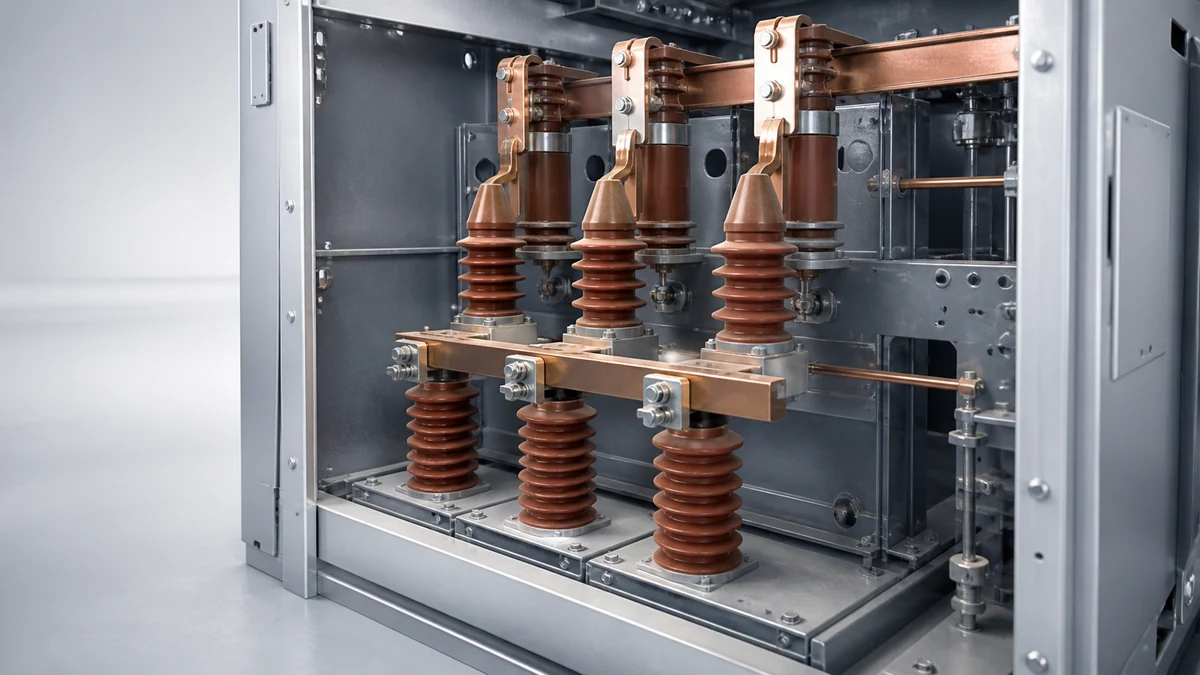
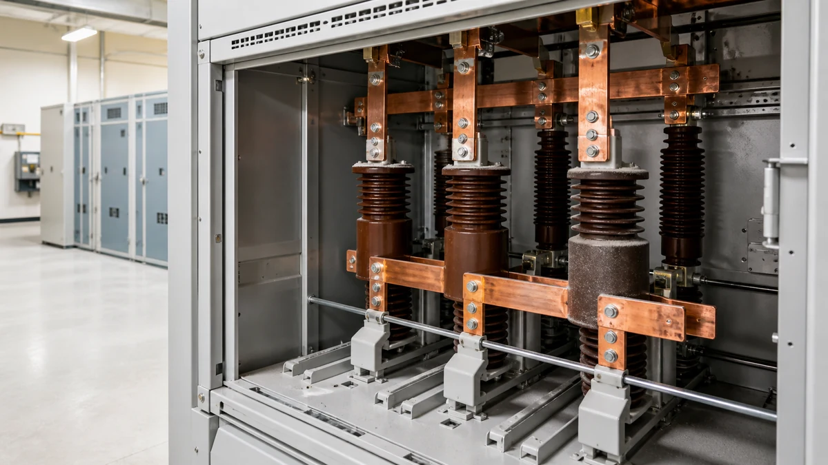
Contamination inspection is specifically about creepage paths — the distances measured along the insulation surface between energized parts and ground or between phases. A contaminated creepage path is functionally shortened because the conductive film eliminates the contribution of the contaminated surface length to the total withstand capability.
Identify the designed creepage distance for each insulator in the equipment from the rating plate or the OEM instruction book. Compare the effective uncontaminated creepage remaining after you map the deposit extent. If the deposit covers substantially the entire creepage path, the insulator should be treated as having no remaining surface withstand margin until cleaned and re-evaluated.
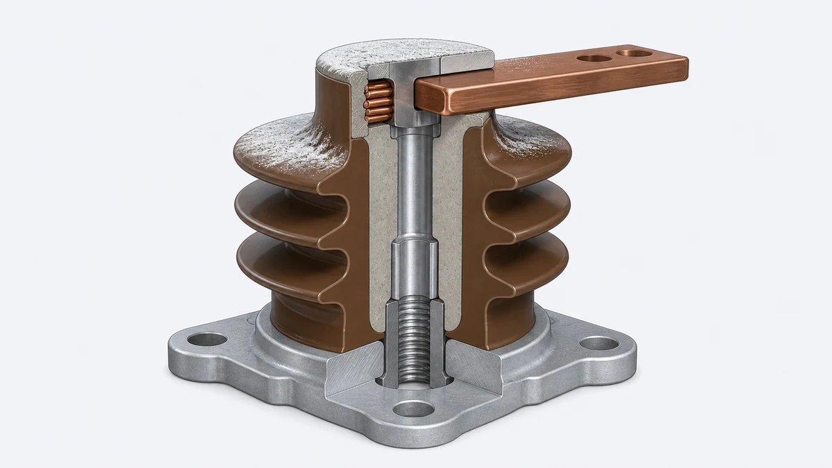
Shed geometry on post insulators and bus-support insulators is designed to protect portions of the creepage path from rain and direct contamination. Inspect the shed undersides and recesses where deposits can accumulate without being visible from above. Contamination in recesses is less easily wetted during normal rain events and can build up to higher conductivity levels than exposed surfaces.
For switchgear with epoxy spout or cone insulators, inspect the cone face and the inner cone surface of the corresponding bushing interfaces. The inner cone contact zone is subject to contamination if the interface is not fully mated or if the mating surfaces have been exposed during previous maintenance. Contamination at the cone interface can track into the cable termination system.
Insulation Resistance and Polarization Index Measurement
Visual inspection findings should be complemented by insulation resistance (IR) measurement before re-energization. IR testing provides quantitative evidence of bulk and surface insulation condition and detects moisture ingress that may not be visible.
Measure IR at the voltages and time intervals specified in the equipment OEM instruction book. A 1-minute IR reading and the polarization index (the ratio of the 10-minute to 1-minute readings) together give a clearer picture than a single reading: a high 1-minute IR with a low PI suggests a surface conduction path that is not visible as tracking but is already degrading withstand margin.
Compare results against previous baseline readings from the equipment service records when available. IR values for MV switchgear insulation are not universally comparable across designs and materials, which is why the OEM instruction book is the authoritative source for interpreting readings for a specific installation. A value that would be acceptable for a porcelain bus support may be unacceptable for a cast-resin component of different geometry and creepage design.
Record temperature and relative humidity at the time of measurement. Both affect IR readings significantly, and the comparison to historical data is only meaningful if conditions are noted. Do not perform IR testing on visibly wet insulation surfaces; allow the equipment to dry to ambient conditions before measuring.
Inspection Decision Workflow and Escalation Points
The table below maps inspection findings to decision paths. It is a decision framework, not an acceptance table — acceptance limits must come from the equipment-specific OEM instruction book.
Finding
Field Disposable
Requires Escalation
Light, dry surface deposit, no discharge evidence
Possible — per OEM cleaning guidance
If deposit extends across full creepage path
Tracking (any extent)
No
Yes — OEM or qualified testing contractor
Streaked discoloration
No
Yes — assess for surface degradation extent
Cracks (any, on stressed surface)
No
Yes — per OEM instruction book
Wet or hygroscopic deposit, no discharge evidence
Conditional — dry first, re-inspect
If any other finding is present
Low IR or PI result
No
Yes — determine cause before re-energization
Evidence of in-service arcing or flashover
No
Yes — complete fault analysis before any re-energization
Escalation does not necessarily mean the equipment is unserviceable. It means the decision to re-energize requires more information or a higher level of technical authority than a field inspection team can provide. An OEM field engineer or a certified electrical testing contractor can perform dielectric testing, surface analysis, and comparative measurements that go beyond what is achievable with portable instruments in a substation bay.
Where the OEM instruction book specifies cleaning methods, those methods are specific to the insulation material and surface coating in that design. Schneider Electric's Masterclad instructions make this explicit: cleaning and maintenance guidance is model-specific and must not be copied to a different switchgear or insulation material without OEM confirmation. Applying a cleaning solvent or technique from one manufacturer's instructions to another manufacturer's equipment can cause surface damage, residue contamination, or swelling of polymer insulation, any of which may reduce withstand capability rather than restore it.
Replacement and Component Verification Decision Points
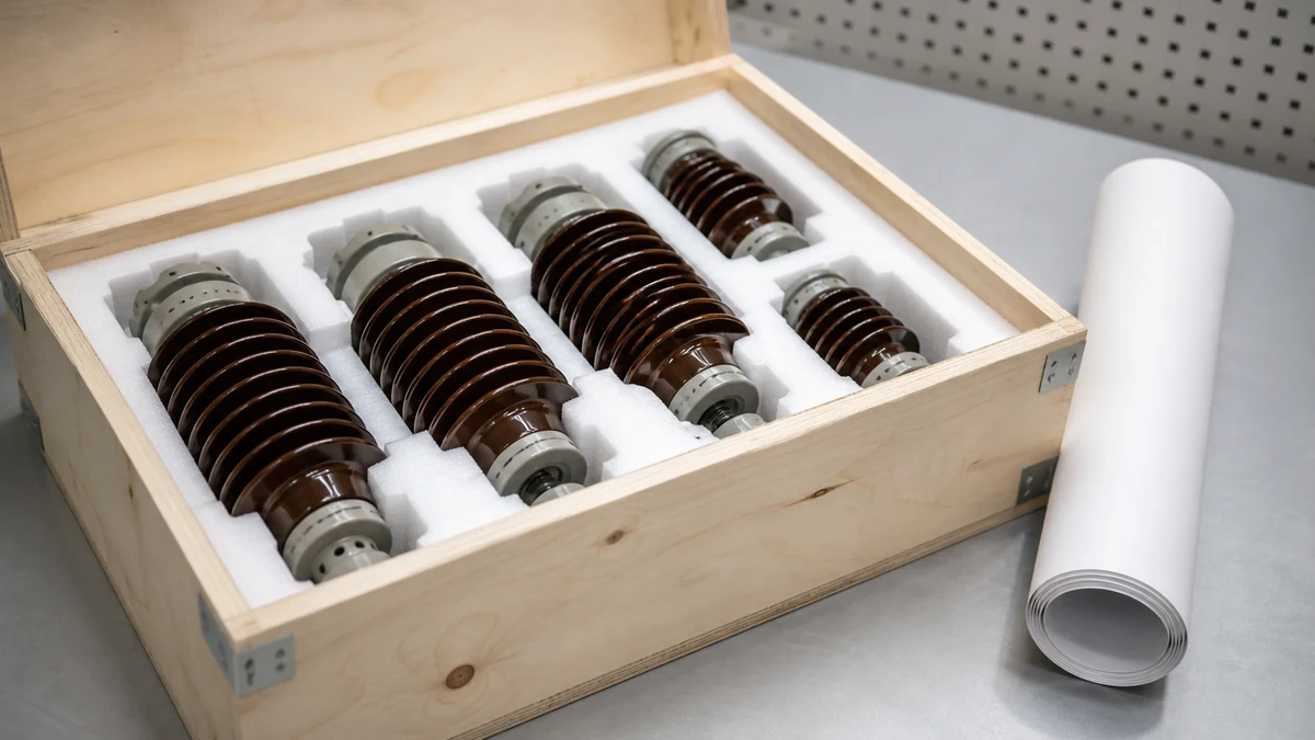
When inspection findings justify insulator replacement rather than cleaning and re-testing, the replacement component must match the original's electrical and mechanical specification exactly. For epoxy resin bus-support insulators, spout insulators, or barrier systems, the critical parameters are the rated voltage, the impulse withstand voltage (BIL), the creepage distance, the insulation class, and the mechanical cantilever or compressive load rating.
Dimensionally compatible parts from different manufacturers are not necessarily electrically equivalent. Creepage distance can be achieved through different shed geometries. Surface treatment and tracking-resistant filler content differ between manufacturers and product generations. The relevant question for procurement is not whether a replacement insulator will physically fit, but whether it will provide the same or greater withstand performance under the contamination and operating conditions of the installation.
Request material certification, test reports, and the applicable IEC or IEEE type test evidence from the supplier. IEC 60071 and IEC 60815 provide the underlying framework for insulation coordination and contamination performance respectively, but the switchgear equipment-level type test is the authoritative demonstration that the installed assembly meets the design intent. A replacement component that has not been validated in the context of the switchgear assembly leaves the equipment operating outside the bounds of its type-tested configuration.
For integrated switchgear insulation — components that are part of the bus assembly, the interrupter housing, or the cable termination interface — consult the OEM before ordering or fitting a third-party replacement, because interface dimensions, contact forces, and dielectric coordination assumptions may all be involved.
Pre-Re-Energization Verification Checklist
Before closing on a re-energization decision, confirm each of the following against the equipment-specific instruction book:
All inspection findings documented with photographs and measurements
No active tracking, streaked discoloration, or unexplained cracks on any HV-stressed surface
IR and PI measurements taken, recorded with temperature and humidity, and within OEM-defined ranges or consistent with historical baseline
Contamination deposit removed or confirmed by measurement to be below the threshold at which it affects creepage withstand — per OEM cleaning guidance, not generic practice
All replacement components verified against OEM specification and installed per OEM torque and assembly instructions
All ground connections restored and lockout/tagout devices removed in the correct order per the site energy isolation procedure
Any escalation findings resolved by OEM confirmation or qualified third-party assessment, with written documentation
Relevant service records updated with inspection date, findings, and corrective actions taken
The re-energization decision is made by a qualified person with authority over the equipment, not by the inspection team in isolation. The inspection team's deliverable is a documented finding set that supports that decision — or that surfaces the information needed to escalate it.
FAQ
What is switchgear insulator contamination inspection?
Switchgear insulator contamination inspection is the systematic visual, physical, and electrical assessment of MV switchgear insulation components to identify contamination deposits, surface discharge damage, cracks, and other conditions that could compromise dielectric withstand before the equipment is returned to service. It includes documentation of findings, comparison against OEM condition criteria, and a structured escalation path for findings that cannot be resolved in the field.
What is tracking on a switchgear insulator and why does it matter?
Tracking is the progressive carbonization of an insulation surface caused by repeated partial discharge activity along a contamination-assisted leakage current path. It is irreversible — the carbonized material is permanently conductive — and it reduces the effective creepage distance of the insulator with each successive discharge event. ABB specifically calls out tracking as a primary finding requiring management under equipment-specific instructions. Any insulator showing tracking evidence must be escalated before re-energization.
What is the difference between cleaning guidance from one manufacturer and another?
Cleaning guidance is model- and material-specific. Schneider Electric's Masterclad instructions state explicitly that their cleaning and maintenance guidance applies to that model and must not be copied to a different switchgear design or insulation material without OEM confirmation. The reason is that solvents, mechanical methods, and surface treatments interact with the insulation material in ways that vary by polymer chemistry, surface coating, and shed geometry. Applying the wrong method can cause surface degradation, residue contamination, or mechanical damage that reduces withstand performance rather than restoring it.
What is insulation resistance testing and when should it be done for contaminated switchgear?
Insulation resistance testing measures the resistance of the insulation system at a defined DC voltage, typically with readings taken at one and ten minutes to calculate the polarization index. For contaminated switchgear, it provides quantitative evidence of surface and bulk insulation condition, particularly when combined with visual inspection findings. It should be performed after the equipment has dried to ambient conditions, before re-energization, and with temperature and humidity recorded so results can be compared to historical baseline data from the equipment's service record. Interpretation of IR values must follow the OEM instruction book for the specific equipment, not generic tables.
What is the role of an OEM instruction book in a contamination inspection?
The OEM instruction book is the authoritative document for defining what constitutes an acceptable condition, what cleaning methods are approved for the insulation materials in that design, and what findings require escalation beyond field maintenance. ABB's and Schneider Electric's instructions both treat their respective guidance as model-specific. Neither establishes universal acceptance limits applicable to another manufacturer's equipment. The decision to re-energize after a contamination event must therefore be grounded in the instruction book for the specific equipment being assessed, not in cross-manufacturer guidance or generic industry practice.
LEO Chen
With more than 20 years of industry experience, LEO Chen has worked with major companies on switchgear, transformer components and medium-voltage equipment projects. He contributes practical guidance for engineers and sourcing teams, with a focus on clear selection criteria, application context and the information needed to prepare an informed RFQ. Connect with LEO on LinkedIn.