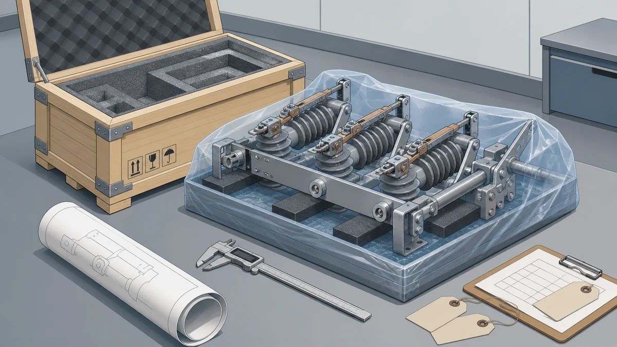
Send the request type, manufacturer, equipment model/year, part reference, ratings, quantity, destination, required date, and any drawing or photo notes. The SUVELL team will review the request.
Email: admin@suvell.com
Phone: +86 189 6871 1705
Factory: No.208 Wei 12 Rd, Yueqing Economic Development Zone, Wenzhou, Zhejiang, China
Two-Position vs Four-Position Transformer Loadbreak Switches: Selection Questions
Selecting a two-position or four-position transformer loadbreak switch starts with the required circuit arrangement. This guide compares open/close switching with configuration-dependent sectionalizing and source selection, highlighting blade geometry, operating sequence, fluid application, and protection questions that must be resolved from the installed documentation.
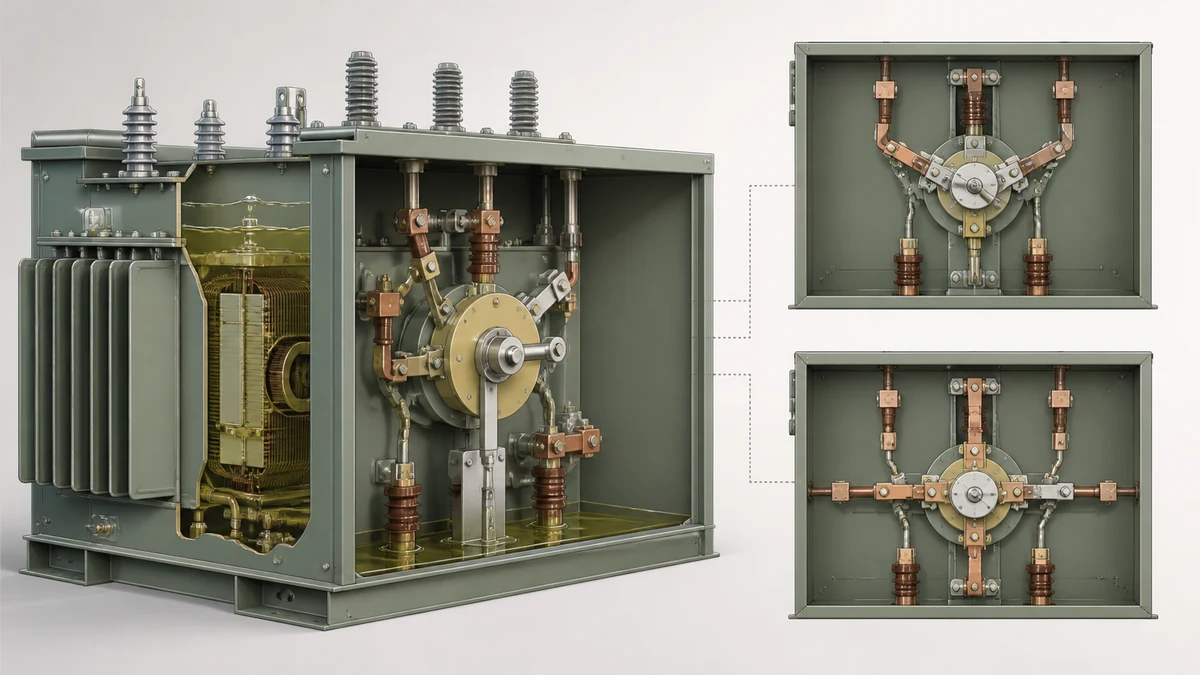
Two-position switches provide open/close switching; the four-position designs discussed here support sectionalizing or alternate-source arrangements with a defined sequence.
Confirm the installed blade configuration and source states from the approved drawing; make-before-break is a specific variant, not a universal four-position feature.
Check the documented fluid application, electrical duty, handle interface, and protection coordination before specifying a replacement or source-transfer arrangement.
The choice between a two-position and a four-position loadbreak switch is fundamentally a system topology question, not a hardware preference. If your transformer application requires alternate-source selection — switching between two independent supply circuits while maintaining load continuity — a four-position sectionalizing switch addresses that requirement in a single device where two separate two-position switches would otherwise be needed. If your application only requires a single-source open/close function, a two-position switch is the correct and simpler fit.
Attribute
Two-Position Switch
Four-Position Sectionalizing Switch
Primary function
Single-source load switching (open / close)
Alternate-source selection between two supplies
Typical position count
Open, Closed
Source 1 closed / Source 2 open; both open; Source 1 open / Source 2 closed; (configuration-dependent)
Make-before-break capability
Not inherent
Available as a design variant per Eaton catalog
Equivalent alternative
N/A
Can replace a pair of interlocked two-position switches
Installed in
Fluid-filled pad-mounted transformers, distribution switchgear
Fluid-filled pad-mounted transformers, distribution switchgear
Configuration dependency
Lower; single-source blade and mechanism
Higher; blade choice and operating sequence are configuration-dependent
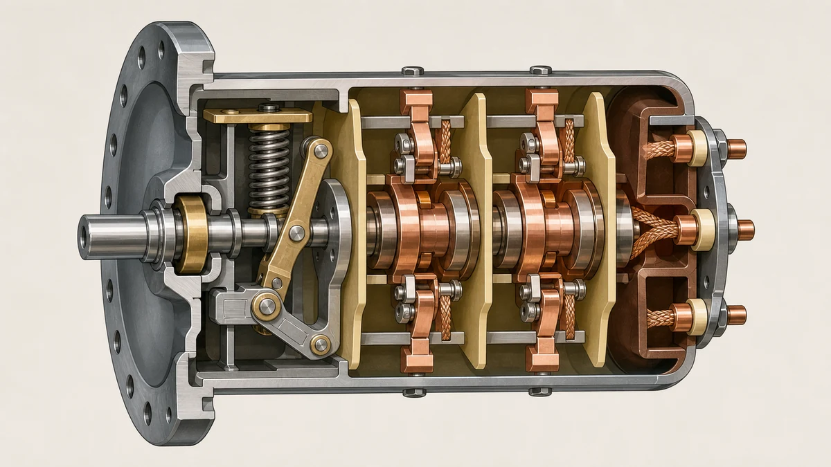
A four-position sectionalizing switch rotates through a defined sequence of blade positions that connect or disconnect two source circuits relative to a common load bus. The positions are not arbitrary; each represents a specific source-connection state, and the transition path between positions is set by the installed configuration.
Eaton's Cooper Power series catalog documents this explicitly: the switch rotates between intended positions, blade selection depends on the installed configuration, and make-before-break variants are available. That last point matters for load continuity. In a make-before-break arrangement, the incoming source is connected before the outgoing source is fully interrupted, eliminating the momentary de-energized interval that occurs in a break-before-make sequence. Which variant is installed — and whether it is appropriate for your load and protection scheme — must be confirmed from the approved drawing and catalog data for that specific unit, not inferred from the switch type alone.
The four-position design also provides an "both open" position, which serves as a visible isolation state during maintenance. This is a distinct operational advantage over a simple transfer scheme built from two-position switches with external interlocking.
Why Eaton Distinguishes This from Two Two-Position Switches
Eaton's transformer OEM equipment documentation explicitly separates the four-position sectionalizing design from two-position loadbreak arrangements and describes the four-position switch as potentially simplifying a design that would otherwise require multiple two-position switches. That distinction is manufacturer-specific. It does not establish a universal equivalence rule or mean that any two-position switch can be freely substituted into a four-position application, or vice versa.
The practical implication is real, though: a four-position sectionalizing switch integrates the mechanical interlocking between sources into the switch mechanism itself. A scheme using two independent two-position switches requires external interlocking — mechanical, electrical, or both — to prevent both sources from being simultaneously connected to the load bus. That interlocking must be designed, specified, and verified separately. The four-position switch pushes that logic into the device, which reduces field-assembly complexity but increases the configuration verification burden at the device level.
Configuration Dependencies That Affect Selection
Both blade geometry and operating sequence in a four-position switch vary by configuration. The Eaton Cooper Power series catalog documents that blade choices are configuration-dependent, meaning the physical hardware differs between units even within the same product family. This has direct consequences for replacement procurement: ordering a four-position switch by type designation alone is not sufficient. The installed blade configuration must be confirmed from the unit's nameplate, the as-built drawing, or the original purchase documentation.
For two-position switches, the configuration dependency is lower because the application is simpler — one source, one load, open or close. Blade ratings, interrupting capacity, and voltage class still require verification, but the positional logic does not add another variable.
Operating sequence in a four-position switch is drawing-controlled. The approved drawing defines which position is reached by which rotational step, and that sequence cannot be determined by inspecting the switch in isolation. An engineer or technician performing a source transfer must work from the approved drawing; the switch itself does not display position labeling that is meaningful without that reference.
Interrupting Ratings and Fluid-Filled Environments
Loadbreak switches in fluid-filled pad-mounted transformers operate in an insulating fluid environment that directly supports arc interruption during load switching. The fluid quenches the arc drawn when contacts separate under load. This means the interrupting rating of a loadbreak switch is not transferable to a dry-type or air-insulated application — the mechanism depends on the fluid.
When evaluating either switch type for replacement or new installation, the interrupting rating on the nameplate must be matched to the maximum load current the switch will be required to interrupt in service. A switch that is rated for the available fault current but not for the service load current at the operating voltage is incorrectly applied. Both parameters require verification from the unit's documentation and the system study data.
Selection and Verification Workflow Before RFQ or Replacement
Before issuing an RFQ or specifying a replacement, the following data points need to be resolved from primary sources — the approved drawing, the original purchase order, and the equipment nameplate — rather than from field observation alone.
**For any loadbreak switch replacement:**
– Confirm the installed switch type (two-position or four-position) from the approved drawing, not from visual inspection alone, since four-position switches in mid-travel or unusual positions can be misread.
– Pull the original catalog number from the nameplate or purchase records. Eaton's Cooper Power series uses catalog number structures that encode voltage class, interrupting rating, blade configuration, and operating sequence; a partial catalog number produces an incomplete specification.
– Verify the fluid type and volume in the transformer. Loadbreak switch ratings are fluid-specific; a switch rated for one dielectric fluid is not automatically rated for another.
– Confirm the BIL and maximum continuous current rating against the system study for that service point.
**For four-position switches specifically:**
– Identify the operating sequence from the approved drawing before specifying a replacement. Make-before-break and break-before-make variants are not mechanically interchangeable in most cases.
– Confirm the blade configuration from the original catalog data. Two units with the same voltage and current ratings may have different blade geometries based on their installed configuration.
– Verify that the protection scheme on both source circuits is coordinated for the switching sequence the four-position switch performs. A make-before-break operation momentarily parallels two sources; protection must account for that condition if the sources are not from the same bus.
**For two-position switches:**
– Verify that the application is genuinely single-source. If the transformer has provisions for an alternate source that are not currently in service, the correct specification may be a four-position switch even if only one source is presently connected.
– Confirm handle and vault interface compatibility if the switch is operator-accessible from outside the transformer enclosure.
Installation and Failure Risks Specific to Each Type
Incorrect installation of a four-position switch is harder to detect and has more serious consequences than the equivalent error on a two-position switch, because the failure mode may not manifest until a source transfer is attempted under load conditions that differ from those present during commissioning.
A common risk with four-position switches is operating the switch to a non-intended intermediate position — a partial rotation that leaves contacts in a state not represented on the approved drawing. This can occur if the operating handle reaches its travel stop before the intended position is fully seated, or if the mechanism is operated from the wrong starting position. Both conditions produce arcing or contact damage that may not trip protection immediately but will degrade the switch over subsequent operations.
For two-position switches, the predominant installation risk is exceeding the interrupting rating during a switching operation. If the load current at the moment of switching exceeds the switch's interrupting rating — which can occur during motor starting, transformer inrush, or fault conditions that have not yet operated upstream protection — the arc will not be cleanly interrupted, and contact damage or tank overpressure can result.
What the Evidence Does and Does Not Support
The Eaton catalog and OEM equipment documentation cited here describe Eaton-specific product design and application guidance. They establish that Eaton's four-position sectionalizing switch is distinct from two-position arrangements, that it supports make-before-break switching as a design variant, and that it can reduce the component count in an alternate-source scheme. This evidence applies to Eaton Cooper Power series products in fluid-filled pad-mounted transformers and distribution switchgear.
This evidence does not establish that four-position loadbreak switches from other manufacturers share the same operating sequence logic, blade configurations, or make-before-break implementation. It does not establish interchangeability between manufacturers. And it does not define the final switching scheme for any specific installation — that remains governed by the approved drawing, the applicable utility or owner specifications, and the protection coordination study for that installation.
Any claim that a switch meets the requirements of a specific application must be supported by the manufacturer's catalog data for that switch and verified against the approved drawing for that installation. Catalog type equivalence does not constitute application equivalence.
—
FAQ
What is a four-position loadbreak switch?
A four-position loadbreak switch is a switching device used in fluid-filled pad-mounted transformers and distribution switchgear to select between two independent source circuits. It rotates through a defined sequence of positions — typically including source 1 connected, both sources open, and source 2 connected — allowing a load to be transferred between sources. Eaton's Cooper Power series documents this as a sectionalizing loadbreak switch, with configuration-dependent blade choices and make-before-break variants available.
What is a two-position loadbreak switch?
A two-position loadbreak switch is a switching device with two states: open and closed. It connects or disconnects a single load circuit from a single source. It is the standard load-switching component in fluid-filled distribution transformers where no alternate source selection is required.
What is make-before-break switching in a transformer loadbreak switch?
Make-before-break switching is a contact sequence in which the incoming source circuit is connected before the outgoing source circuit is fully interrupted. This maintains load continuity during a source transfer by eliminating the brief de-energized interval that occurs in a break-before-make sequence. Eaton documents make-before-break as a design variant within its four-position sectionalizing loadbreak switch product line. Whether make-before-break is appropriate for a specific application depends on the protection coordination for both source circuits, since the switch momentarily parallels two sources during the transition.
What is a sectionalizing loadbreak switch?
A sectionalizing loadbreak switch is a loadbreak switch designed to section a distribution system — dividing it into independently switchable segments — or to select between alternate supply sources. In the context of fluid-filled pad-mounted transformers, Eaton uses this term specifically for its four-position design that supports alternate-source selection. The term distinguishes this device from simple two-position open/close switches used for single-source load switching.
What is the significance of the approved drawing for loadbreak switch selection?
The approved drawing for a transformer or switchgear assembly defines the operating sequence, installed blade configuration, source circuit assignments, and positional logic for the loadbreak switch in that specific unit. For four-position switches, the approved drawing is the authoritative reference for which switch position corresponds to which source state and which rotation direction reaches which position. No replacement or operating decision for a four-position switch should be made without the approved drawing, because the switch mechanism does not carry enough labeling to determine operating sequence independently.
LEO Chen
With more than 20 years of industry experience, LEO Chen has worked with major companies on switchgear, transformer components and medium-voltage equipment projects. He contributes practical guidance for engineers and sourcing teams, with a focus on clear selection criteria, application context and the information needed to prepare an informed RFQ. Connect with LEO on LinkedIn.