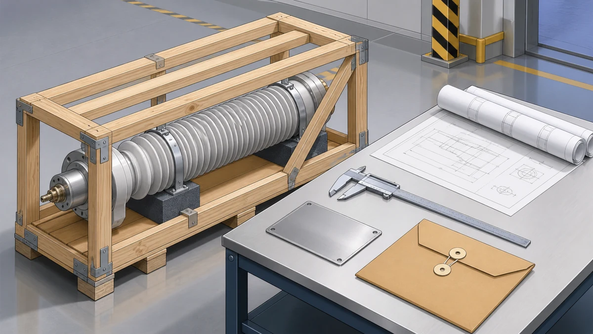
Send the request type, manufacturer, equipment model/year, part reference, ratings, quantity, destination, required date, and any drawing or photo notes. The SUVELL team will review the request.
Email: admin@suvell.com
Phone: +86 189 6871 1705
Factory: No.208 Wei 12 Rd, Yueqing Economic Development Zone, Wenzhou, Zhejiang, China
High-Voltage vs Low-Voltage Transformer Bushings: How the Interfaces Differ
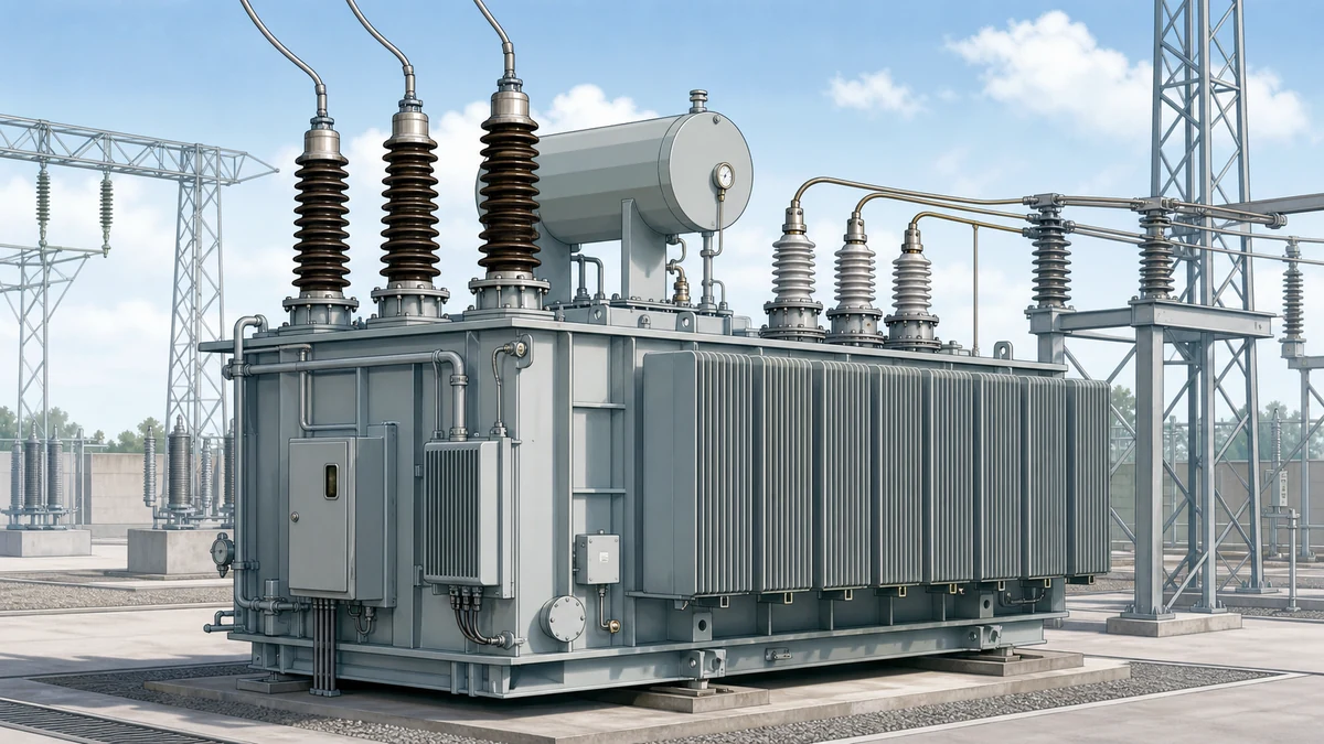
HV and LV transformer bushings share insulating and supporting functions but place different demands on their interfaces. This comparison covers dielectric stress, current and heat, insulation technologies, and connection loads, then identifies the drawing and test records needed for a position-specific replacement review.
HV bushing selection emphasizes dielectric stress and creepage, while LV selection gives greater weight to current, heating, and connection loads.
Record the insulation technology and, for capacitively graded designs, the available capacitance and dissipation-factor baseline alongside the electrical ratings.
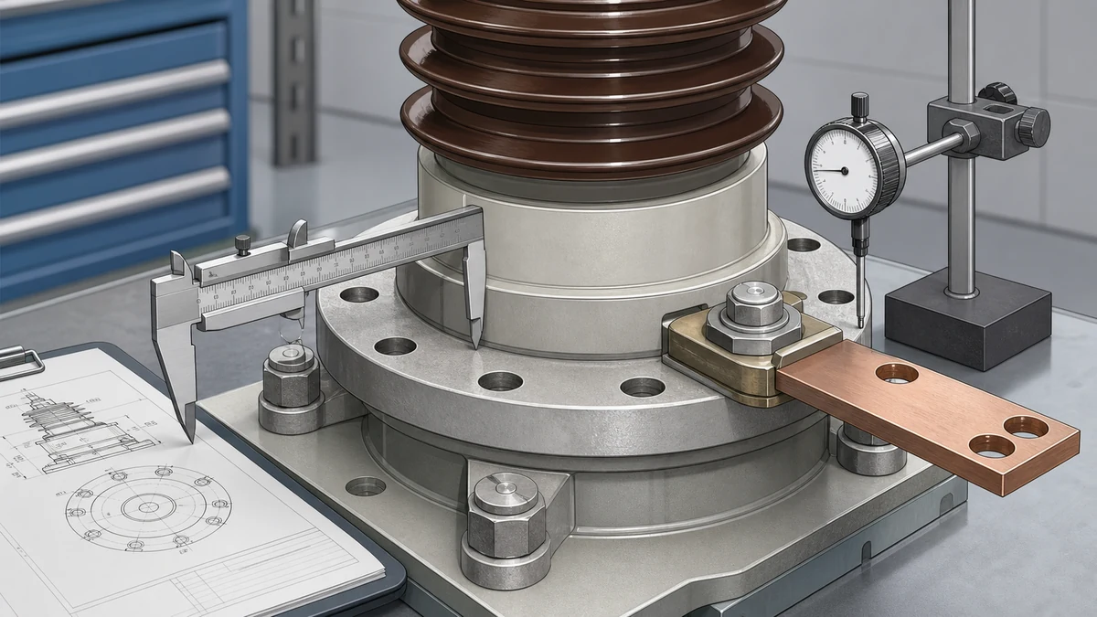
Verify flange geometry, installation angle, terminal arrangement, and mechanical loading against the transformer interface drawing before approving a replacement.
Transformer bushings are engineered interfaces, not generic parts with a voltage label. HV selection is led by dielectric stress. LV selection is led by current, heat, and the mechanical load of its connection.
That difference changes the insulation system, terminal arrangement, test record, and replacement data. A nameplate match alone does not prove a replacement fits.
The Short Answer
Selection point
High-voltage bushing
Low-voltage bushing
Dominant duty
Control electric-field stress and external creepage
Carry high current without excessive heat or connection load
Terminal geometry, thermal capacity, and busbar load
Replacement record
Technology family, capacitance/tan δ, flange, and creepage data
Current rating, conductor geometry, flange, and terminal data
The table is a starting point, not an interchangeability rule. The transformer drawing and the original bushing data remain decisive.
What a Bushing Actually Does at Each Interface
Per Hitachi Energy's documentation on transformer bushings, a bushing provides an insulated conducting path through a grounded barrier. It also supports that conductor mechanically. Both functions exist on both sides of the transformer, but their relative importance changes at each interface.
On the high-voltage (HV) side, the electric field stress across the insulation system is the dominant engineering concern. The conductor is operating at a high potential relative to the grounded tank wall through which it passes, and the bushing must manage that stress gradient over the full distance from tank flange to the terminal at the top. The insulation column must prevent flashover along its surface, partial discharge within its dielectric, and thermal runaway caused by dielectric losses accumulating under sustained voltage.
On the low-voltage (LV) side, voltage is lower but current is substantially higher — often by the same transformer turns ratio. This shifts the design emphasis toward thermal and mechanical performance. The conductor cross-section must handle continuous rated current without excessive resistive heating, and the mechanical loading from heavy busbars or cable terminations connected to the LV terminal can be significant. The LV bushing still has an insulation system, but its dielectric stress regime is far less severe than the HV equivalent.
This distinction — field stress dominance on the HV side versus current and mechanical loading dominance on the LV side — explains most of the dimensional, material, and configuration differences that follow.
Insulation Technology Families and Where They Apply
Hitachi Energy identifies three primary insulation technology families relevant to modern transformer bushings: OIP (Oil-Impregnated Paper), RIP (Resin-Impregnated Paper), and RIS (Resin-Impregnated Synthetic). Understanding which technology is matched to which interface requires understanding what each technology manages.
OIP bushings use paper wound around the conductor, subsequently dried and impregnated under vacuum with mineral oil. The oil-paper system has a long service history and excellent dielectric properties, but it contains oil — which means sealed joints, expansion accommodations, and monitoring for oil level and condition. OIP designs are heavily represented on HV interfaces above transmission voltages precisely because their dielectric properties at high field stress have been validated over decades. They are less suited to environments where oil-free construction is mandated, such as indoor GIS installations or locations with stringent fire-risk requirements.
RIP bushings use epoxy resin in place of oil for impregnation, eliminating the oil-containment requirements and making the bushing inherently dry-type. The resin-impregnated paper core is dimensionally stable and does not require oil level monitoring. RIP designs are common across a range of voltages and appear on both HV and LV interfaces in modern transformers, particularly where dry-type or indoor construction is required.
RIS bushings substitute a synthetic fiber material for paper in the wound core, with resin impregnation retained. This addresses certain limitations of paper-based systems in terms of moisture sensitivity and thermal cycling behavior. RIS technology is encountered at higher performance requirements where the paper-based dielectric may introduce unwanted variability.
Technology selection is not simply voltage-driven. It depends on voltage class, installation environment, cooling medium, and interface configuration. A LV bushing on a large autotransformer may therefore need a more demanding insulation system than an HV bushing on a small distribution transformer.
Field Grading Changes the HV Evidence Record
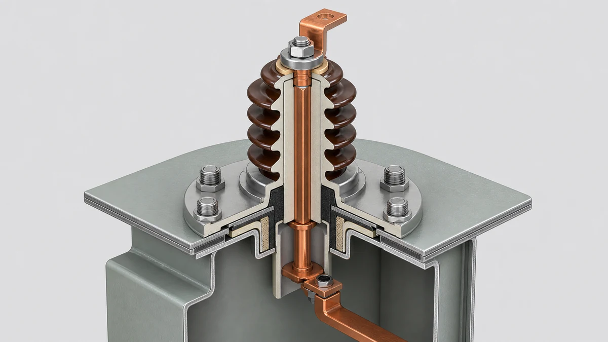
The HV interface must control field concentration at the conductor, flange, and terminal. Capacitively graded designs use conducting layers within the insulation to spread that stress. This limits partial discharge and gives the bushing a defined capacitance and dissipation-factor (tan δ) baseline.
That baseline is useful after commissioning. A material change in capacitance or tan δ can indicate an insulation problem before a visible failure occurs. LV bushings usually do not use the same grading structure, so their replacement evidence is more focused on current, terminal, and mechanical compatibility.
Mechanical Interface: Flange, Cantilever Loading, and Sealing
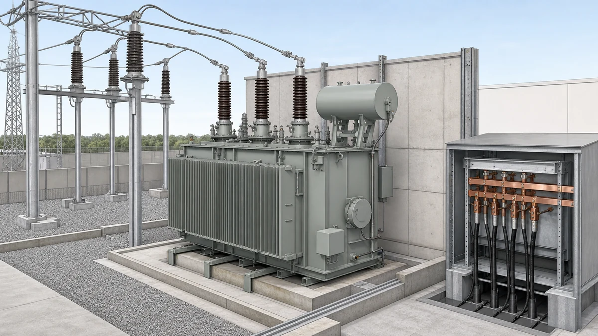
Both HV and LV bushings mount through the transformer tank wall or lid via a flange, but the mechanical loading environment differs. LV terminals often accept large copper or aluminum busbars, which are heavy and relatively stiff. Their cantilever load must pass through the terminal and flange without cracking the porcelain or composite housing or fatiguing the tank seal.
HV terminals, particularly at transmission voltages, connect to overhead conductors or SF6-insulated bus via flexible connections specifically intended to decouple the bushing from rigid mechanical loads. The terminal fitting geometry and the conductor end seal are designed around this connection type. Connecting a stiff rigid busbar to an HV terminal in a way that applies direct cantilever force is an installation error — one that may not be visually obvious but will create fatigue cracking at the flange or housing over thermal cycling.
Oil-filled transformer bushings, primarily OIP designs, must seal against the internal oil and the external environment. Flange geometry is specific to the transformer's tank penetration. HV and LV positions are not interchangeable merely because voltage and current ratings match. The installation angle must also match the original design exactly.
Standards Scope: What IEC 60137 Governs and What It Does Not
IEC 60137:2017 covers characteristics and type tests for insulated bushings for AC apparatus, including transformers, with a highest voltage for equipment above 1,000 V. It defines test voltage levels, test methods, and the type-test requirements that a bushing must satisfy to be rated for a given voltage class.
IEC 60137 does not establish interchangeability. Two compliant bushings at the same rated voltage can still be wrong for the same transformer position. Interchangeability also requires a matching flange, seating geometry, current rating, technology family, terminal arrangement, and dimensional envelope.
IEC 60137 compliance is necessary, not sufficient. The transformer OEM's interface specification is the binding record for the remaining fit check.
Failure Modes by Interface Position
HV and LV bushings fail differently, and understanding the failure modes informs both inspection strategy and the urgency of response to an anomalous test result.
On the HV side, common long-service failures include moisture ingress, progressive partial discharge, and oil deterioration in OIP designs. They usually develop slowly. Rising tan δ and partial-discharge readings can provide an early warning. Thermal imaging can also reveal losses at the grading structure or terminal contact. If ignored, the failure can end in a flashover that damages the bushing and sometimes the transformer.
On the LV side, sustained overcurrent and high contact resistance are more common concerns than pure dielectric failure. Oxidized contacts, loose fasteners, and incorrect busbar torque create resistive heating. That heat can crack a porcelain or composite housing before routine electrical tests show a problem. Excessive busbar cantilever load can drive a similar fatigue process.
Contamination of the outer creepage surface matters on both sides but is more consequential on the HV side due to the higher voltage gradient. For outdoor installations in pollution-heavy environments, the specified creepage distance must match the IEC pollution severity category for the site. Undersized creepage on the HV bushing in a coastal or industrial pollution environment is a known failure driver that IEC 60137 type testing alone will not catch — the site category must be part of the original specification.
Replacement Checklist Before RFQ or Approval
Start with the transformer nameplate and the original documentation. Confirm the winding position, highest voltage for equipment, continuous current, cooling medium, and existing bushing technology. Then obtain the transformer manufacturer's bushing interface drawing for that position.
Before approving a spare or issuing a procurement RFQ, verify:
insulation family: OIP, RIP, or RIS, and any approved technology change;
flange bolt pattern, seating face, installation angle, CT accommodation, and body envelope;
terminal geometry at the conductor end and transformer end;
required creepage distance for the actual site;
current rating and mechanical load from busbar or line hardware; and
applicable type-test evidence, plus capacitance and tan δ records for a graded HV design.
If a requirement applies only to GIS, a tertiary winding, or a specific CT arrangement, state that condition in the RFQ. Do not turn a conditional detail into a generic requirement.
FAQ
What is the primary difference between a high-voltage and low-voltage transformer bushing?
The HV bushing is designed primarily around electric field stress management — controlling the voltage gradient across its insulation over a large potential difference relative to the grounded tank. The LV bushing is designed primarily around current-carrying capacity and mechanical loading, since it handles much higher currents at lower voltage. These different engineering priorities produce different insulation structures, different conductor cross-sections, and different dimensional profiles, even when both bushings are installed on the same transformer.
What is the role of capacitive grading in a transformer bushing?
Capacitive grading uses a series of concentric conducting foil layers embedded within the bushing insulation winding to redistribute the electric field along the bushing's length and radius. Without grading, the field concentrates at the conductor, the grounding flange, and the terminal — the geometrically sharp boundaries of the insulation system — and initiates partial discharge. Grading smooths this distribution into controlled increments. This is an HV engineering requirement; LV bushings operating well below the field stress thresholds that trigger partial discharge do not incorporate it.
What is IEC 60137 and what does it not cover for replacement decisions?
IEC 60137:2017 is the international standard covering characteristics and type tests for insulated bushings used in AC apparatus including transformers, for equipment with a highest voltage above 1,000 V. It defines the test methods and voltage levels that establish a bushing's rated class. However, IEC 60137 explicitly does not establish that two compliant bushings are interchangeable. Compliance with IEC 60137 confirms electrical type qualification; it does not confirm compatibility with a specific transformer's mechanical interface, current rating, technology family, or terminal geometry. Those items require a separate check against the transformer manufacturer's interface specification.
What is the significance of tan δ measurement for transformer bushings?
The dissipation factor, commonly called tan δ, measures the ratio of resistive loss to capacitive reactive power in the bushing's insulation. For OIP and RIP bushings with capacitive grading, tan δ is measured as part of the type test and factory acceptance test, providing a baseline value. In service, periodic tan δ measurement is the primary diagnostic for detecting moisture ingress, insulation aging, or oil deterioration before they reach failure severity. A rising tan δ relative to the commissioning baseline — even while still
LEO Chen
With more than 20 years of industry experience, LEO Chen has worked with major companies on switchgear, transformer components and medium-voltage equipment projects. He contributes practical guidance for engineers and sourcing teams, with a focus on clear selection criteria, application context and the information needed to prepare an informed RFQ. Connect with LEO on LinkedIn.